Starline install installation cards. Installation of StarLine D94 alarm system on Nissan Murano (photo)
Starline alarms are common in our automotive market for their reliability and versatility. Some motorists, in order to save money, own funds are wondering how to independently install these systems on their vehicles. To do this, they will need Starline alarm installation cards.
Where to find connection diagrams for Starline alarms
Due to the fact that Starline models are widespread in our market, the manufacturer of these security systems makes for its products detailed instructions in Russian. Each model, in addition to a detailed user manual, comes with an installation map.
It is necessary for the correct installation of the system, as well as optimal choice areas of the car that are most vulnerable to car thieves, or those who are trying to illegally enter a car that will be under the Starline alarm.
If a driver bought a used car that already has one of the Starline models installed, and he needs to reinstall it, then the official website of the manufacturer of these security systems will come to the rescue. Just type in the search engine “Starline alarm...installation maps” and find the official website.
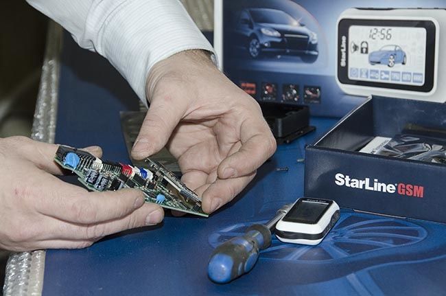
In principle, there is nothing complicated. Approximately the installation instructions will look like in photo No. 1. 
In addition, you can also contact various service centers who do the installation. In some cases, the instructions are left with the car mechanics.
The main thing to remember is that under no circumstances should you use cards from other models, even if they are similar in their functions.
It is interesting to know that ghost alarms are also installed according to diagrams, but they cannot be found in in electronic format on the official website, since the safety zones are different for each brand of car.
Installation procedure
If car enthusiasts decide to connect Starline security systems to their cars themselves, then they need to adhere to the following algorithm.
- Carefully study the instructions. As stated above, the alarm installation map is included as an appendix to the user manual. Therefore, the car enthusiast should find it and study it carefully.
- Selecting the arrangement of elements security system, as well as safety zones. If you carefully study the installation map, you will see that it will indicate in detail how all Starline elements should be connected not only to each other, but also to some components of the power unit (depending on the functionality of the security system). The manufacturer also provides recommended designations for the installation locations of individual sensors, the unit and other elements. These designations will indicate safety zones. You can use the manufacturer’s recommendations, or you can independently determine other installation locations for sensors and other elements, depending on technical features specific car brand.
- Installation . This is the last step, which requires certain skills from the car enthusiast. It should be noted right away that you will have to disassemble the dashboard of the car and carefully examine the installation locations of the sensors on the engine elements. All connections between system elements (wires) must be well sealed and insulated to avoid short circuits or breakdown of wires. At correct installation, the security system will immediately set up and will not malfunction during its operation.
You also need to follow a few tips. The first is that before installation, the car enthusiast must carefully study the requirements regarding the compatibility of the model with electrical wiring car. There are situations when an alarm, due to its energy-consuming capabilities, cannot be installed on a car.
Further recommendations apply to those car enthusiasts who are poorly versed in wiring diagrams. It's better not to do this for drivers independent connection, because they would rather do harm than do right. Even despite the availability of the information provided in the instructions, it is better to entrust the solution to the problem to professionals.
The procedure for installing a flashpoint alarm does not differ from the above, but it is better not to violate the security zones (where the installation of elements and sensors takes place).
Cards for installing Starline are always included with any model of this security system. If they are not there, then you can use the company’s official website and find them in the archive.
Installation anti-theft system Starline is a rather complex procedure that not everyone can cope with. To perform the installation yourself, you need certain knowledge and skills, as well as installation maps. In this article we will share basic recommendations that will help you install the system at home.
When connecting the Starline anti-theft installation, the wiring must be laid away from sources of electrical noise. It's about O high voltage wires, ignition coil and other components. Please note that the wiring should not come into contact with moving parts of the vehicle, namely steering rods, pedals, etc. Installation of wiring connections according to the connection card must be carried out with the battery disconnected (the author of the video is Pro Sto).
If the vehicle is equipped with an air cushion or an encoded receiver, when turning off the power, you must follow the service manual for the car. Installation of all permanent connections without exception must be done using soldering - all connections after connection must be insulated as much as possible.
As for the Starline central alarm unit, here you also need to take into account a few tips. Installation of the unit with other elements should be carried out with the main wiring only after the cable laying has been completed. Each individual Starline alarm model is connected in accordance with the map and service manual. P Before installation, read the instructions carefully!
Tips for installing car alarm components
Below we will give recommendations regarding the installation and installation of the main components of the Starline alarm system in accordance with the diagram. It is immediately necessary to make a reservation that the diagram and installation map may vary depending on the model.
- Transceiver module. This component with the antenna must be connected to the five-pin output installed in the central unit under the opening cover. Installation is carried out using the wire that is included in the anti-theft system.
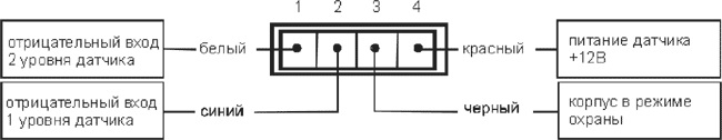
- Installation of a two-level shock detector made using a four-wire cable to the system control unit. When doing the work yourself, you need to correctly set the regulator so that the sound of the siren does not go off just like that. The sensitivity of the regulator, which determines whether the sound is turned on, is adjusted using potentiometers on the regulator body.
- Indicator light. This component, in accordance with the diagram, must be included in the two-pin output. This output is located on the control unit. The LED indicator flashes always when the alarm is on and stops working after it is turned off. It is advisable to display the light bulb itself on the windshield - thus, even at a distance from his vehicle, the driver will always know whether the system is activated or not.
- Valet button.
- Connects in the same way. The Calet button from the Starline alarm must be installed so that an attacker cannot reach it in the event of a vehicle break-in. A similar recommendation applies to the button for activating the anti-robbery mode - it is also connected to the control unit and installed in the cabin. External motor blocking circuit.
- This option for blocking the power unit significantly increases the anti-theft characteristics of the system as a whole, since in the event of hacking, the attacker will face a serious problem. To properly control the element, it must be connected to the black-yellow cable of the system, but before that the connector type must be programmed to HP. This step must be carried out in accordance with the diagram and instructions for installing and operating the Starline alarm system. Connecting the system to optics, i.e. low beam headlights. To make such a connection, you must additional channel , in our case, connect the third one, marked with a yellow-red cable, in accordance with the diagram. The duration of the signal can be configured for ten or thirty seconds, or until the pulse is turned off by the remote control. Please be aware that a light path that is too long can lead to discharge..
- battery Control block, As a rule, it is mounted behind the glove box or under center console
- opposite the driver's seat. It is better not to install this element in the engine compartment, since it contains many sensors and electronic devices that will interfere with the digital signal. The unit is installed using the supplied bolts or ties. Siren. As for the siren, this is one of the main elements, because it is the one that warns the driver with sound about possible penetration into the car. A siren with sound is installed in a place inaccessible to a potential criminal, so it is mounted in the engine compartment. To ensure that the sound is always loud, the siren should not be exposed to moisture or. When exposed to external influences, the sound quality can be significantly reduced, please take this into account. should be posted on metal surface, which is in reliable contact with the body.
System connection diagram

Above is a diagram of the connection of the anti-theft installation. The wiring diagram itself may vary depending on the vehicle model. If you cannot distinguish one circuit element from another, contact an auto electrician for help.
Video “The process of connecting the Starline alarm system”
Using the Starline A93 model as an example, you can familiarize yourself with the nuances and subtleties of installing the system (the author of the video is Yuri Kadyrov).
StarLine D94 is a security and telematics system for protecting SUVs, designed for extreme operating conditions.
The StarLine D94 car alarm has an intelligent autostart, a non-scannable dialog control code, an integrated multi-system CAN module, built-in GSM and an optional GPS interface, a 512-channel noise-resistant transceiver with a range of up to 2000 m, and a shock-resistant control key fob that can withstand falls from a height of up to 3 meters.
A modern radio channel allows the StarLine D94 security and telematics complex to control the system at a distance of up to 1000 m and receive alert signals at a distance of up to 2000 m from the vehicle. In turn, flexible settings for service channels will ensure the implementation of the wildest wishes of car owners.
The StarLine D94 alarm system provides reliable, stable operation in an extended temperature conditions from -50 to +85 °C. This allows the StarLine security complex to be used in varied and harsh climatic conditions.
The alarm unit of the StarLine D94 security and telematics complex ensures silent operation and protection of power outputs from accidental short circuits thanks to power switches. The silent operation of the alarm unit makes it much more difficult for car thieves to find it, and small sizes ensure high secrecy of its placement inside the car.
The built-in GSM module allows you to manage security and service functions, as well as receive notifications about the security status on your mobile phone. And smartphone owners can control the car alarm using a special free application.
The StarLine D94 car alarm key fob has an original design that matches its off-road character. Owner StarLine 4x4 can choose the color of the key fob from the included overlays: deep blue, burgundy or snow white. The ability to choose a color allows you to make your keychain recognizable, which can be useful in large companies in off-road conditions. In addition, the key fob has a larger display and convenient buttons that allow you to use the alarm while wearing gloves. Pleasant blue backlighting and an image of an SUV, as well as intuitive icons, make using StarLine 4x4 comfortable and highlight the owner of the car.
Below, together with Starline specialist Andrey Maslov, we will analyze in detail the installation of the StarLine D94 alarm system on a 2003 Nissan Murano (including an alarm installation map).
Stage 1. Preparing the car for alarm installation.
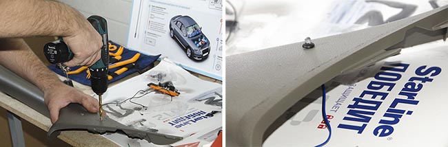
Before installing an alarm system on a car, you must first protect the paint surface of the body parts and interior trim elements so as not to damage them during the work.

Protecting the paintwork of the car fender is necessary so that during installation the wires from the lamp and soldering iron do not scratch the surface, since some of the work will be done under the hood.
Covering the seat with a special protective film is also a rule of good manners. Although the work of an electrician requires clean hands, during work you have to come into contact with dirty elements of the car, such as the engine or inner space doors. In this case, the master’s hands, his clothes and tools may become dirty. In order not to spoil or accidentally stain the interior trim or damage it with a tool, the seats are covered with a special protective cover, which, for reliability, can be fixed with paper tape with easily removable glue.
The next step is to disassemble the instrument panel in order to free the car's electrical circuit blocks necessary for installing the alarm. When performing this work, be careful not to damage the fasteners of the instrument panel parts.
To remove the instrument panel on a Nissan Murano, you must first remove bottom part(the so-called torpedo). To do this, you need to unscrew the screws and remove the latches. Then you need to disconnect the climate control hose and its sensor.
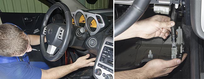
After removing the lower part of the instrument panel, you need to remove the steering casing. To do this, unscrew the screws - there are three of them on the Nissan Murano. You also need to disconnect the steering column position adjustment lever. After which the metal plate is removed, which is secured with two 10 M 6 screws.

When the disassembly of the Nissan Murano instrument panel is completely completed, you need to free the vehicle control units and standard wiring to gain access to it. If necessary, the blocks must be removed from the fasteners.
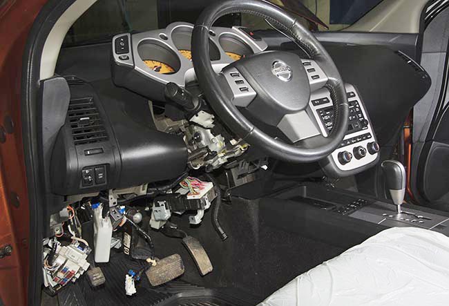
When access to all the necessary blocks and standard wiring of the car is free, and the tool is laid out, you can proceed to the further stages of installing the alarm.
But before that, we carefully remember what the standard wiring looks like: upon completion of the work, it should be as similar as possible to the factory one.
Stage 2. Preparing the StarLine D94 alarm system for installation on a Nissan Murano.
With the set of wires supplied with the StarLine D94 alarm system, an electrician must do maximum amount operations on the desktop to facilitate further installation and make it more accurate.

Starline specialists strongly recommend soldering all connections when installing an alarm system on a car. As you know, electrical engineering is the science of contacts. All other connection options do not provide a reliable connection, and poor contact can lead to serious malfunctions of both the alarm and the car as a whole.
To solder connections you need to use rosin. Unlike soldering with acid, which causes premature corrosion of the metal at the soldering points, contacts soldered with rosin will last the entire service life of the car.
The resulting connections are insulated, excess wires are cut off.

To do this, the StarLine D94 alarm unit is disassembled and the card is installed in the groove located next to the CAN module (chip labeled StarLine). If the car does not have a CAN bus, it can be removed.
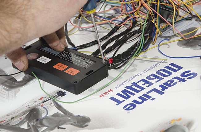
The assembled StarLine D94 alarm unit is now ready for installation on the car.
Stage 3. Connecting the alarm circuits to power cables vehicle on-board network 12V
This and the next stage of alarm installation will concern work with the BCM body control unit. This is one of the typical connection points for the permanent plus signal (three red wires of the 18-pin connector X1 and the red wire of the relay module).
When connecting the StarLine D94 alarm system to a standard electrical wiring wire, you must use wires with a cross-section of at least 6 square meters. mm. It is recommended to connect the power supply of the car alarm unit and the relay module to different circuits protected by different fuses.

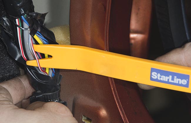
There are many connections made to the StarLine D94 alarm system on the power harness of the ignition switch. Connects here remote start engine (autostart), the ignition itself, central locking, turn signals, brake pedal, trunk and door limit switches, as well as a starter. On a Nissan Murano, two starter wires are connected to the ignition switch, and to implement autostart, you must connect to both wires. This can be done using a regular four-pin auxiliary relay.
To begin connecting the Starline D94 alarm system to a Nissan Murano, you need to remove the standard insulation to gain access to the wires. First you need to find a permanent plus - the ignition power wire. For Nissan Murano this is the green wire.
All connections are soldered and insulated.

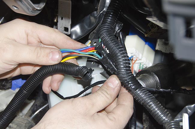
The wires are carefully laid in a corrugated tube, since under dashboard there may be moving parts such as the steering column. Laying the wiring in a corrugated tube is mandatory, since only it provides reliable protection wires from abrasion and short circuit.
Stage 4. Connecting limit switches
In order to find the limit switches, you need to ring the wiring. We find the limit switches of the doors, trunk, hood, brake pedal.
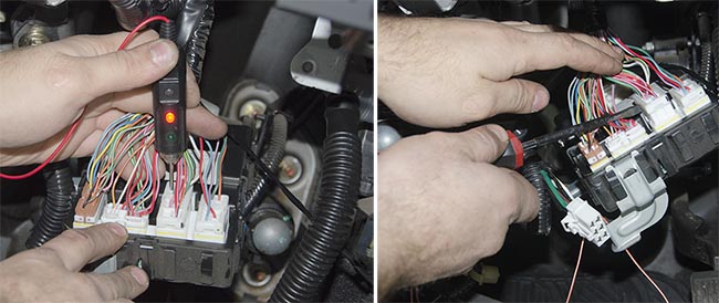
Turn signal switches, left and right, on Nissan Murano have green wires with a black stripe.
![]()


![]()
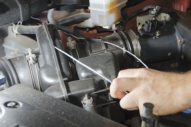
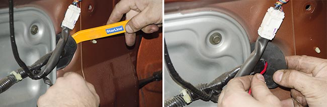
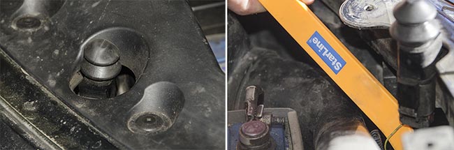
The hood lock limit switch must be removed from the passenger compartment under the hood in order to then connect it to the standard limit switch. To do this, the end switch must be pulled using a metal conductor cable (broach), to which the wires are attached using electrical tape, through a standard seal.

The Nissan Murano rear door limit switches are located under the left and right kick panels, which must be carefully snapped off.

We open the standard wiring and find the rear door limit switches. For Nissan Murano, the limit switches are red wires with a white stripe.

After connecting to the alarm to the rear door limit switches, return to the wiring standard view and install the removed parts in place.
Stage 5. Connecting the StarLine D94 alarm system to the car’s central locking
To connect the alarm to the central locking control, you need to pull two wires, responsible for closing and opening the lock, into the door through the standard seal.

Before this, the alarm wires must be connected to the ignition switch wires. After connecting, solder the contacts, insulate them and place them in a corrugated tube.
After completing the necessary connections in the wiring (turn signals, front door switches, trunk switch) of the BCM and fuse box, we prepare the wires for connection to the car's central locking.
When removing the door trim, it is advisable not to damage the clips, their attachment points and the trim itself. Therefore, first you need to find all the screws and unscrew them. Nissan Murano has two screws in the door handles that are easily located: they are located under the decorative plugs.

Now you need to carefully try fastening the door trim in areas where there are obviously no screws - some of the fasteners will be on clips and can be snapped off this way. The test made it possible to find out that the driver's door trim of the Nissan Murano is attached not only to the found screws - some of the screws are hidden.

After removing the power window and door lock control unit, you need to unfasten the terminals. Beneath them in the Nissan Murano there will be three more screws securing the door trim. Now the door trim can be easily removed.
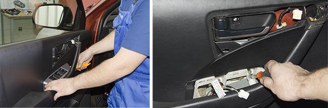
Before final dismantling of the trim, you need to disconnect the door locks and the door light terminal.
![]()
The easiest way to remove the removed Nissan Murano door trim is to put it in the trunk.
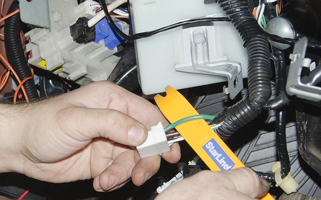
Now you need to ring the wiring to find the central locking control wire.

We remove the standard insulation to make a neat connection.
The control wires for the central locking of the Nissan Murano are as follows: locking the door - blue, unlocking - red. To find out which one is responsible for what, it is necessary to apply an impulse. Locking the door is a single pulse, unlocking is a double pulse. If you set the door to lock for 30 seconds, the StarLine D94 alarm will work in “comfort” mode, i.e. the glass closer will work.
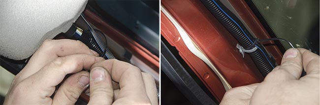
To retract the wires, you need to bend the standard seal. The wires are pulled through a standard seal, which must be carefully pierced with a thin tool, such as a screwdriver.
We pull the alarm wires from the central lock through it and solder them with those that came from the alarm unit.
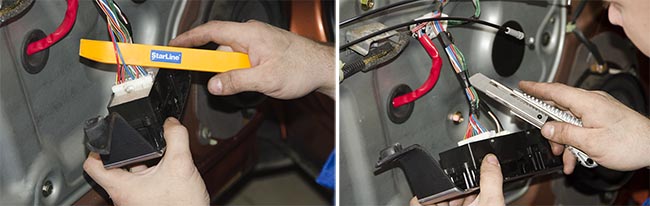
To connect to the central alarm unit, you need to remove the speaker and feel the wires with your hand.

The soldered wires of the standard Nissan Murano wiring and alarm are insulated and laid in corrugation. Laying wiring in the door is mandatory, since there are mechanisms that can damage the wires.
The new wire is attached with clamps to the standard wiring.

Step 6. Connecting the car alarm antenna
To connect the StarLine D94 alarm antenna to the Nissan Murano, you need to remove the left decorative panel windshield pillars and secure the antenna wiring.
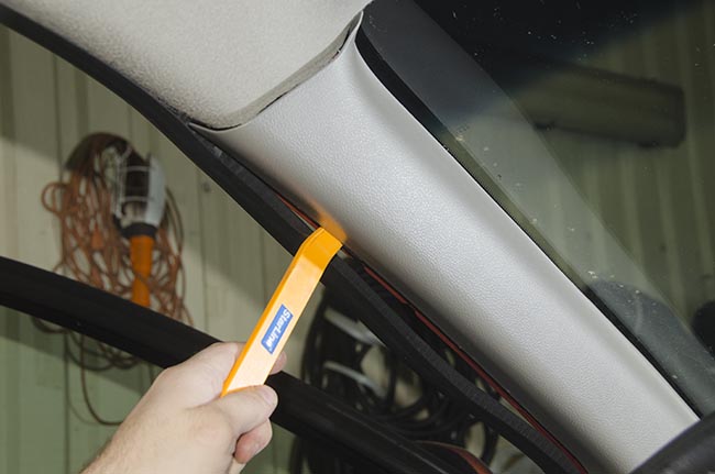
There is no need to lay the antenna wiring in the corrugation here - there are no moving mechanisms in this place, and there is little space, so it will be difficult to stretch the corrugated tube.
When attaching the StarLine D94 alarm antenna, several factors need to be taken into account. Firstly, it is desirable that the antenna be located a few centimeters from the metal parts of the body. Secondly, the antenna should not come into contact with the silk-screen printing (tinting or darkening coating of the windshield), since it significantly impairs the reception and transmission of the signal.
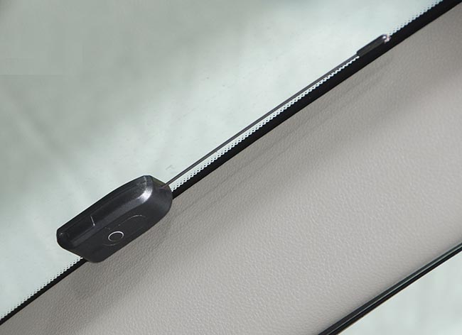
IN decorative trim A hole is made in the Nissan Murano windshield pillar with a 6.5 mm drill, into which the StarLine D94 LED alarm indicator is inserted.
There is no need to cut the alarm antenna wire: everything is neatly folded and twisted, thereby forming a neat bundle. The resulting harness is attached to the standard wiring.

After installing the service button in any convenient place, all the main connections of the StarLine D94 alarm system under the dashboard of the Nissan Murano are made: the system is completely assembled, but not laid down. Next, you will need to make connections under the hood and install a bypass module for the standard Nissan Murano immobilizer.

Before installing the immobilizer bypass module, you need to check the operation of the alarm system. If everything works, you can proceed to the final stages of installing the StarLine D94 alarm system.
Stage 7. Installing the immobilizer bypass module and completing work under the dashboard
It is highly advisable to disguise the antenna wire of the immobilizer bypass module as standard wiring. The frame of the immobilizer bypass module is placed on the ignition switch. The masked wire is attached to the standard wiring.

After installing the immobilizer bypass module, the blocks must be secured and the alarm unit installed. In this case, the StarLine D94 alarm unit is attached to the metal surface of the Nissan Murano using double-sided tape. Before installing the unit, the mounting surface must be degreased.
If such an installation is inconvenient or impossible, the StarLine D94 alarm unit has fasteners for clamps or screws that allow it to be installed on the car in another way.
The connectors on the alarm unit can be coated with hot-melt adhesive to ensure increased reliability of connector fastening: the resulting Nissan Murano wiring harnesses are thick and rigid, there is little space under the panel, and in some cases the harness may pull the connector out of its socket during installation. To avoid this you need hot glue.

When installing the alarm unit, please note that the central unit contains a cabin temperature sensor, so it must be placed as far as possible from heat sources, otherwise the temperature readings may differ from the actual temperature in the cabin.
Stage 8. Alarm connections in the engine compartment
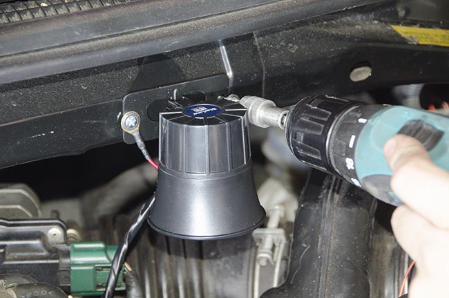
A StarLIne D94 alarm siren is installed under the hood, a Nissan Murano hood lock limit switch is connected, an engine temperature sensor is connected, and the engine control wire is connected to the injector power supply or to the generator operation control wire.
Hood lock limit switch for Nissan Murano - wire yellow color. In order to find it, you need to remove the decorative plastic panel.
Then you need to remove protective cover Nissan Murano engine.

You need to find a stable signal to control engine operation in the engine wiring.
This installation of the StarLine D94 alarm on a Nissan Murano used a tachometer signal on the injectors and spark plug coils. To access these wires, you first need to open the standard injector power wiring.

Now you need to prepare the alarm wiring: securely insulate all soldered connections, lay the wiring in a corrugated tube.

First of all, you need to connect the engine temperature sensor.
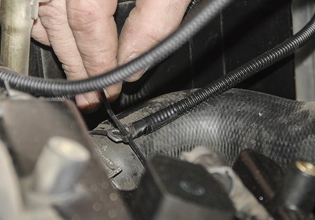
The engine temperature sensor is attached to the rubber radiator pipe of the Nissan Murano. Right choice The location of the sensor largely determines the correctness of the system reading the true engine temperature and thereby contributes to the timely start of the engine based on temperature.
It is very undesirable to mount the engine antifreeze temperature sensor to metal, because In winter it cools down quickly, which is why the sensor does not show the correct temperature. This, in turn, affects the operation of the auto-warm-up function based on engine temperature. So, a situation may arise when the car starts up constantly, although this is not at all required to maintain the desired engine temperature. On the rubber pipe, temperature differences are smaller and the alarm temperature sensor shows the temperature of the antifreeze in the engine more correctly.
The engine temperature sensor is attached to the radiator pipe of the internal combustion engine using a clamp. The temperature sensor wire is additionally fixed with a clamp for greater reliability of wiring fastening.

Now the engine control sensor wire is connected to the injector power wires. Having measured the length of the wire so that the wiring lies in its place, we cut off the excess.
The injector wires need to be additionally ringed to select the one you need, with a more stable signal.


After the engine control sensor is connected, you need to connect the Nissan Murano hood lock switch.
![]()
After connecting, all the wiring is placed in a corrugated tube, the corrugation, in turn, is secured with clamps so that the wiring under the hood does not dangle - you need to avoid the risk of the wiring coming into contact with moving parts of the car.

After checking the operation of all systems, you need to replace all the removed plastic trims: two of them were removed from the Nissan Murano - from the internal combustion engine and above the hood lock limit switch.
Stage 9. Completing the installation of the StarLine D94 alarm system on the Nissan Murano.
Now you need to replace the disconnected blocks in the steering column space and assemble the dashboard into reverse disassembly ok.
When the StarLine D94 security telematics complex is activated, the functions are programmed and all the necessary settings for the operating parameters are made, the alarm installation is completed.

The StarLine D94 alarm system was installed on a Nissan Murano by StarLine specialist Andrey Maslov.
Starline A93 is one of the most modern, versatile and reliable car alarms. The price including installation of the Starline A93 CAN+LIN car alarm is about 15,000 rubles. You can install the Starline A93 security system yourself if you have the appropriate electrical skills. installation work and basic knowledge in the field of electrical engineering, reading electrical diagrams. The device is supplied with an instruction manual and installation instructions for SlarLine A93. During installation security complex First of all, the installation manual will be useful. The main stages of work are described in detail there, electrical circuits. The manual is intended for professional car alarm installers. When installing Starline A93, you must follow the technology for installing electrical equipment, be extremely careful, and take into account the features of the electrical circuit of your car. Let's consider the features of performing individual stages of work.
General requirements
Before starting work, you must study. The security system is designed for installation on vehicles with an on-board voltage of 12 Volts. Thus, it cannot be installed on motor vehicles. In principle, this car alarm can be installed on trucks by powering it from one battery and making galvanic isolation from the electrical equipment of the truck using relays for controlled circuits.
At the first stage of work, an installation map is developed. It shows the installation locations of the main units, the location of the wires, the location of the sensors and the blocking relay.
Before starting installation, you should make sure that all the electrical equipment of the car is working properly; it is better to carry out computer diagnostics.
Electrical installation work must be carried out with the battery disconnected. When removing the battery terminals, make sure that the ignition is turned off, otherwise the standard immobilizer may become untied.
When installing alarm units, rigid connections should be used: self-tapping screws, screw connections, or, in extreme cases, glue. Soft suspension of blocks on plastic clamps significantly reduces the reliability of the system. Installation of Starline A93 requires special attention and thoroughness in all installation work.
Security system conductors should be laid in such a way that they do not come into contact with moving body parts, accelerator, clutch and brake pedals, steering column, or heating climate control systems. It is better to lay all conductors in close proximity to the standard electrical wiring harnesses. At the end electrical installation work and setting up the security system using plastic clamps, you can combine standard and non-standard wiring into a single clamp, thereby complicating the work of possible car thieves.
The manufacturer recommends bridging additionally installed blocking relays with diodes. This means that medium power diodes are installed parallel to the relay winding, connected in reverse polarity relative to the on-board network voltage.
Placement of elements of the security complex
A typical arrangement of the complex components is shown in the figure. 
The center unit (position 1) is usually located under the instrument panel. It should be taken into account that there is a cabin temperature sensor inside the unit, so if it is installed in close proximity to the cabin heater pipes, the temperature data will be incorrect. Typically, installers use the area next to the driver's left knee, installing the center unit behind the fuse box on the left side passenger compartment pillar. You should make sure that this area does not get wet during heavy rain. It is better to install the central unit with the connectors facing down to prevent water from getting inside the housing in extreme cases.
The transceiver (item 2) is installed in the upper part of the cabin to ensure maximum control range. It is necessary that there are no other electronic components near it (at a distance of less than 5 cm), metal parts salon
The security system status indicator light (3) is usually installed in the corner of the passenger compartment under the windshield.
The siren (pos. 4) is installed under the hood away from heat sources. In case of prolonged operation sound signal Overheating and failure of the siren is possible, so it is better to include an additional 5 Ampere fuse in the siren's electrical circuit.
Engine temperature sensor 5 is mounted on metal parts of the cooling system, preferably near the thermostat in close proximity to standard sensors vehicle coolant temperature. Limit switches The trunk and hood are installed in such a way that when completely closed there is a gap of approximately 3 mm.
Location and purpose of contacts on the central unit
Contact layout on the Starline A93 main unit. 
All main connectors of the central unit are located in a row on one side. This simplifies installation work and routing of conductors. Starline connectors are universal, so in order, for example, to replace a Starline a91 with an a93, you just need to “switch” the connectors on the head unit.
Pinout (location and purpose of pins) of the main connectors. 

Connecting main circuits
The alarm installation begins with connecting the power wires to the electrical units. The ground (minus power) should be connected under the standard bolts for securing the grounding wires of the vehicle. They are usually located in bottom corners front part of the passenger compartment or in the area of the passenger compartment fuse box. If such fastening points are not found, you can independently make mass fasteners to the metal body parts of the car under the dashboard.
When connecting to + power, use stranded copper wire with a cross-section of at least 6 sq. mm in polyvinyl chloride insulation. All electrical connections of wires should be made using the “twisting + soldering” method, followed by insulating the connection point with heat shrink. 
Connecting to data buses and control circuits
Connection to CAN and LIN buses is made in accordance with the connector diagram 
For correct operation of CAN and LIN buses, you should familiarize yourself with how the operation of these interfaces is organized in your car. If your car does not support central locking and light signals via CAN bus, you should use the following diagram connections. 
The Starline A93 security complex provides four ways to control the central lock:
- low current control;
- force positive control;
- force negative control;
- two-wire control.
The connection diagram for low-current control is shown in the figure. 
Power control connection diagram 
The StarLine A93 system provides various options engine blocking. The most common option is shown in the figure 
The preferred blocking is usually blocking the voltages supplied to the injectors and the fuel pump power circuit. This blockage stops the supply of fuel to the engine, thereby making it impossible to start the engine. At the same time, a power failure of these devices does not lead to the accumulation of engine errors, as when, for example, the ignition coil is blocked in gasoline engines. This method has its drawback: almost all car thieves know about it. It is not difficult for an experienced specialist to bypass these blockages within three minutes. No one will do this under the window, but by transporting the car away from the place of theft, you can start it.
Therefore, Starline A93 provides additional low-current blocking channels. In using additional locks, you can show originality by blocking some sensor, without which the engine or drive will not start automatic transmission gear changes to make transporting the vehicle more difficult.
Connecting the immobilizer bypass module and GSM module
To organize the autostart mode, the car alarm system provides an immobilizer crawler. An example of connecting a VR-03 lineman is shown in Fig. 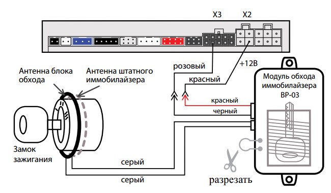
The security complex provides for the connection of a GSM module. It can be purchased separately or supplied as a kit. 
Type of GSM module board 
Installation GSM module produced directly into the central unit. To do this, it is disconnected from the connectors and disassembled. Then the GSM module is installed in the connectors on the central device board. 
The general signaling diagram of Starline A93, Starline A93 ECO, Starline A63 is shown in Fig. 
The connection diagram for controlled modules and sensors is shown in Fig. 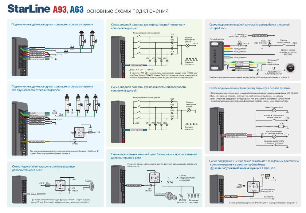
Setting up the Starline A93 security system
After completing all electrical work, check once again for correctness. electrical connections, check for short circuits and breaks in electrical circuits. After this, a trial activation of the complex is performed. To do this, connect the battery terminals to the vehicle's on-board network. At this moment, it is imperative that the key fobs with the batteries inserted are at hand. During the initial start-up, it is possible that the alarm will immediately enter the security mode, the siren will sound, and the doors may be locked. If the car has problems opening door locks from a mechanical key, it is better to open the windows in case the doors are blocked.
After disarming the vehicle, a test start of the engine is performed. If it is successful, turn off the engine and check for errors in the vehicle systems using computer diagnostics. If there are no new errors, proceed to system programming burglar alarm according to the tables provided in the installation and maintenance manuals.
Advantages of self-installation of a security system
Installing an alarm system yourself has a number of advantages:
- the cost of installation is significantly reduced, mainly consisting of the cost of consumables (wires, heat shrink, fasteners);
- at self-installation it is possible to implement non-standard methods of blocking the engine, which will significantly complicate the problem of car theft;
- repair and maintenance yourself installed alarm system won't be difficult.
StarLine car alarms are a modern security system. Depending on the model, they are equipped with auto engine start, radio control dialogue code and more protection points. The system is not susceptible to intelligent hacking, which makes it extremely reliable. Installation is easy if you use the StarLine alarm installation card and have minimal skills.
Additionally, it is possible to install a module to bypass the standard immobilizer. The siren is also connected. These parts can be supplied as part of the car alarm kit. When making a connection, you need to connect all the points to be protected. Using the manufacturer's installation cards, the StarLine security system will optimally perform its functions after installation.
Installation procedure car alarms StarLine is a complex and time-consuming process. To make it easier, you should use an official map from the manufacturer. Experts say that it has some shortcomings that will have to be taken into account. Their correction depends on the specific situation. Motorists should select diagrams that are suitable for a specific car model.
You can find them on the official website of the StarLine company or in other sources. They are also included in every alarm kit. Alarm and additional devices supplied in a box with accessories.

Typical scheme connections Starline a91 dialog
The process of installing a car alarm can be done in the garage or outside, if weather conditions permit.
The interior is being dismantled. 
The VSM unit is being installed. 
Installation of the alarm system is not possible without pinout of the VSM unit.
Oxidation may occur where alarm wires are connected to standard wiring. All twists must be soldered thoroughly. This will avoid operational problems that arise from poor-quality installation. 
To insulate the contacts, a gas soldering iron, solder and flux are used.
The central unit of the security system is installed.
Upon completion of the work, programming of several parameters of the security complex is carried out. For this, a diagram corresponding to the make and model of the car is used. While working, do not rush to avoid serious mistakes. 
Using installation cards from the manufacturer StarLine, the installation of a car alarm on a car will be done with high quality. Doing it yourself will allow you to connect all the points and isolate the contacts carefully. Craftsmen at car dealerships often make mistakes by doing work in a hurry. Connecting the alarm yourself will save a lot. 