Sound signals when trains move. Fire alarm: types and actions of personnel at the site
Purpose and tasks of the PS
Fire alarm is a set of technical means for detecting a fire, processing, presenting a fire notification in a given form, special information and (or) issuing commands to turn on automatic installations fire extinguishing and technical devices.
The main tasks of the functioning of the fire alarm system in conjunction with organizational measures are the tasks of saving lives and preserving property. Minimizing damage during a fire directly depends on the timely detection and localization of the fire source.
Terms and Definitions
A fire alarm loop is a communication line in the fire alarm system between the control panel, fire detector and other technical means of the fire alarm system
Fire detectors – technical means, designed to detect fire factors and/or generate a fire signal. There are various fire factors - smoke, heat, open flame.
Reception and control devices are multifunctional devices designed to receive signals from detectors along alarm loops, turn on light and sound annunciators, provide information to central monitoring panels, and provide procedures for controlling the state of zones (loops) using controls. As controls, you can use remote and built-in keyboards with secret codes, as well as readers together with electronic identifiers (cards and keys).
Sounders are devices for notifying people about an alarm at an object using sound or light signals.
VUOS – remote optical display device. Designed to determine the location of a triggered detector (if the detectors do not have their own addressable device).
Principles of detecting fire factors
In fire alarm systems, detectors are designed to detect a specific fire factor or combinations of factors:
- Smoke. When assessing this factor, the detector analyzes the presence of combustion products in the air in the volume of the protected room. There are two most common types of detectors that operate upon detection of smoke:
- Detectors that perform local (point) control of the optical density of air entering the optical chamber of the detector when moving air flow in room. To do this, an infrared LED and a photodetector are installed in the optical chamber of the fire detector at a certain angle. In the detector's standby mode, infrared radiation from the LED does not reach the photodetector. However, if there is smoke in the optical chamber, its particles scatter infrared radiation, and it reaches the photodetector. When the reflected light flow is higher than the set value, the smoke detector generates a fire alarm signal.
- Detectors that monitor the optical density of air in a certain volume (linear detectors). These detectors are two-component, consisting of an emitter and a receiver (or one unit of receiver-emitter and reflector). The receiver and transmitter of such a detector are located near the ceiling on opposite walls of the protected room. In standby mode, the transmitter signal is detected by the receiver. In the event of a fire, smoke rises to the ceiling, reflecting and scattering the transmitter signal. The receiver calculates the ratio of the level of the current value of this signal to the signal level corresponding to the signal in standby mode. When a certain threshold of this value is reached, a fire alarm notification is generated.
- Warm. In this case, detectors evaluate the value and increase in temperature in the protected room. Heat detectors are divided into:
- Maximum – generating a fire notification when previously set temperature values are reached environment;
- Differential - generating a fire notification when the rate of increase in ambient temperature exceeds the established threshold value;
- Maximum-differential - combining the functions of maximum and differential thermal fire detectors.
- Open flame. Flame detectors respond to factors such as the radiation of a flame or smoldering fire. Flame various materials is a source of optical radiation that has its own characteristics in various regions of the spectrum. Accordingly, different combustion sources have their own individual spectral characteristics. Therefore, the type of sensor is selected taking into account the characteristics of the radiation sources located in its field of action. Flame detectors are divided into:
- Ultraviolet - use the range from 185 to 280 nm - the ultraviolet region;
- Infrared - react to the infrared part of the flame spectrum;
- Multispectral - responsive to both the ultraviolet part of the spectrum and the infrared. To implement this method, several receivers are selected that are capable of responding to radiation in different parts of the source radiation spectra.
- A special place is given to the detection of fire factors directly by a person through his senses. In such cases, manual fire call points are installed in fire alarm systems to manually activate the fire alarm.
Types of Fire Alarms
Non-addressable (traditional) fire alarm system
In such systems, control panels determine the state of the alarm loop by measuring electricity in an alarm loop with detectors installed in it, which can only be in two static states: “normal” and “fire”. When a fire factor is detected, the detector generates a “fire” notification, abruptly changing its internal resistance and, as a result, the current in the alarm loop changes.
It is important to separate alarm notifications from service notifications associated with faults in the alarm loop or false alarms. Therefore, the entire range of loop resistance values for the control panel is divided into several areas, each of which is assigned one of the modes (“Normal”, “Attention”, “Fire”, “Fault”). Detectors are connected to the alarm loop line in a certain way, taking into account their individual internal resistance in the “normal” and “fire” states.
For traditional systems, such features are provided as the ability to automatically reset the fire detector power supply in order to confirm the activation, the ability to detect several triggered detectors in a loop, as well as the implementation of mechanisms to minimize the influence of transient processes in the loops.
Addressable threshold fire alarm system
The difference between an addressable threshold signaling system and a traditional one lies in the topology of the circuit design and the algorithm for polling sensors. The control panel cyclically polls connected fire detectors to find out their status. Moreover, each detector in the loop has its own unique address and can already be in several static states: “normal”, “fire”, “fault”, “attention”, “dusty”, etc. Unlike traditional systems, such a polling algorithm allows you to determine the location of a fire with accuracy down to the detector. Fire regulations in Russia, it is allowed to install one addressable detector to detect a fire, provided that when this fire detector is triggered, a signal is not generated to control fire extinguishing installations or type 5 fire warning systems.
Addressable analogue fire alarm system
Addressable analogue systems are currently the most progressive; they have all the advantages of addressable threshold systems, as well as additional functionality. In analogue addressable systems, the decision about the state of the object is made by the control device, not the detector. That is, in the configuration of the control device, response thresholds are set for each connected addressable device (“Normal”, “Attention” and “Fire”). This allows you to flexibly create fire alarm operating modes for rooms with varying degrees of external interference (dust, level of industrial smoke, etc.), including during the day. Control device constantly polls connected devices and analyzes the received values, comparing them with the threshold values set in its configuration. In this case, the topology of the address line to which the detectors are connected can be circular. In this case, a break in the address line will lead to the fact that it will simply split into two radial independent loops, which will fully retain their functionality.
The listed features of addressable analogue systems provide such advantages over other types of fire alarm systems as early detection of fires and a low level of false alarms. Monitoring the performance of fire detectors in real time allows you to identify detectors that are promising for maintenance in advance and draw up a plan for specialists from the service organization to visit the site. The number of protected premises by one controller is determined by the addressable capacity of this controller.
About the applicability of systems
At first glance, it is advisable to use traditional systems at small and medium-sized facilities, when one of the main selection criteria is the relatively low cost of the system. And the cost of the system is largely determined by the cost of the detector. Today, conventional non-addressable detectors are relatively cheap. Despite the fact that the use of modern digital signal processing algorithms in control and control devices can significantly increase the reliability of signal detection from detectors, and as a result, reduce the likelihood of false alarms, it is still necessary to take into account that often such detectors do not provide a sufficient level of reliability. And - as a consequence of this fact - the need to install at least two or even three detectors in one room. Traditional systems do not provide ease of installation - the loops in such systems can only be radial. Accordingly, the larger the system, the more communication lines need to be installed and the more detectors to install.
When the reliability criterion comes to the fore, we can already talk about installing an addressable threshold or addressable analogue system at the site.
At the same small and medium-sized facilities, it is advisable to use addressable threshold systems that combine the advantages of addressable analog and traditional systems. In this case, we can already install one detector in the room (the cost of which is slightly lower than the cost of an addressable analog detector), a free line topology (bus or ring), and there is no need to use VUOS for addressable detectors. However, it is worth considering that for such systems it is not possible to use short-circuit insulators in the loop, and also to determine the exact location of breaks ring loop. Maintenance of such systems is also carried out in a preventative manner.
Analogue addressable systems do not have such disadvantages. The advantages of installing such systems are obvious - a free topology plus the ability to use short-circuit insulators and determine the location of a line break, the ability to set analog values for alarm messages "Attention", "Fire" (and these values may be different for day and night), as well as for value of "Dust content". When using an addressable analogue system, savings on maintenance are obvious - monitoring the performance of fire detectors in real time allows you to identify detectors that are promising for maintenance in advance and draw up a plan for specialists from a service organization to visit the site. In the software of addressable analogue microcontrollers detectors from the Bolid company have implemented algorithms that eliminate false alarms under various environmental influences
Non-addressable fire alarm system using ISO Orion devices
To build a non-addressed fire alarm system in the Orion integrated security system manufactured by the Bolid company, you can use the following control panels with monitoring of radial alarm loops:
- Signal-20P;
- Signal-20M;
- Signal-10;
- S2000-4.
All devices, with the exception of Signal-20P, can operate in autonomous mode. However, when using devices to organize fire alarms, the system usually also uses a network controller - the “S2000M” (or “S2000”) remote control. The console in PS systems can perform functions of displaying events occurring in the system, as well as relay control functions if additional relay modules are used. If display units are required, a remote control is also required.
Depending on the type of connected fire detectors, when programming device configurations, the loops can be assigned one of the types:
Type 1. Fire smoke with double trigger recognition.
Fire smoke detectors (normally open) are included in the AL.
- “Open” – loop resistance is more than 6 kOhm;
When the detector is triggered, the device generates the message “Sensor Triggered” and re-queries the alarm loop state: it resets (short-term switches off) the loop power supply for 3 s. If within 55 seconds after the reset the detector is triggered again, the alarm loop switches to the “Attention” mode. If the detector does not trigger again within 55 s, the alarm loop returns to the “Armed” state. From the “Attention” mode, the AL can switch to the “Fire” mode if the second detector in this AL is triggered, as well as after the time delay specified by the parameter “Transition delay to Alarm/Fire”. If the parameter “Transition delay to Alarm/Fire” “Transition delay to Alarm/Fire”, equal to 255 s (the maximum possible value), corresponds to an infinite time delay, and the transition from the “Attention” mode to the “Fire” mode is possible only when the second detector in the alarm zone is triggered.
Type 2. Firefighter combined single-threshold.
The alarm system includes fire smoke (normally open) and heat (normally closed) detectors.
Possible modes (states) of AL:
- “On guard” (“Armed”) – the alarm system is controlled, the resistance is normal;
- “Disarmed” (“Disarmed”) – the alarm system is not controlled;
- “Attention” – a heat detector has been triggered or a smoke detector has been triggered again;
- “Fire” - expired after the detector was triggered “Transition delay to Alarm/Fire”;
- “Short circuit” – loop resistance is less than 100 Ohms;
- “Open” - loop resistance is more than 16 kOhm (more than 50 kOhm for “S2000-4”);
- “Failure to arm” - the alarm system was violated at the moment of arming.
When the heat detector is triggered, the device switches to the “Attention” mode. When a smoke detector is triggered, the device generates the message “Sensor Triggered” and re-queries the AL status (see type 1). When the detector is confirmed to be triggered, the AL switches to the “Attention” mode.
From the “Attention” mode, the AL can switch to the “Fire” mode after the time delay specified by the parameter has expired “Transition delay to Alarm/Fire”. If the parameter “Transition delay to Alarm/Fire” is 0, then the transition from the “Attention” mode to the “Fire” mode will occur instantly. Parameter value “Transition delay to Alarm/Fire”, equal to 255 s (the maximum possible value), corresponds to an infinite time delay, and the transition from the Attention mode to the Fire mode is impossible.
Type 3. Fireman's thermal two-threshold.
Fire thermal (normally closed) detectors are included in the AL.
Possible modes (states) of AL:
- “On guard” (“Armed”) – the alarm system is controlled, the resistance is normal;
- “Disarmed” (“Disarmed”) – the alarm system is not controlled;
- “Arming delay” – the arming delay has not ended;
- “Attention” – the activation of one detector is recorded;
- “Fire” - the activation of more than one detector is recorded, or after the activation of one detector the “Transition delay to Alarm/Fire”;
- “Short circuit” – loop resistance less than 2 kOhm;
- “Open” - loop resistance is more than 25 kOhm (more than 50 kOhm for “S2000-4”);
- “Failure to arm” - the alarm system was violated at the moment of arming.
When the detector is triggered, the device switches to the “Attention” mode for this alarm loop. From the “Attention” mode, the device can switch to the “Fire” mode if the second detector in the alarm loop is triggered, as well as after the time delay specified by the “Transition to Alarm/Fire Delay” parameter has expired. If the “Transition to Alarm/Fire Delay” parameter is equal to 0, then the transition from the “Attention” mode to the “Fire” mode will occur instantly. The value of the “Transition to Alarm/Fire Delay” parameter, equal to 255 s (the maximum possible value), corresponds to an infinite time delay, and the transition from the “Attention” mode to the “Fire” mode is possible only when the second detector in this alarm zone is triggered.
For each loop, in addition to the type, you can configure additional parameters such as:
- Delay of transition to Alarm/Fire - for any of the fire loops this is the time of transition from the “Attention” state to the “Fire” state. Loops of type 1 and type 3 (with double trigger recognition) can also go into the “Fire” state when the second fire detector in the alarm loop is triggered. If the “Delay for transition to Alarm/Fire” is 255 s, then the device does not switch to the “Fire” mode in time (infinite delay). In this case, loop types 1 and 3 can go into the "Fire" state only when the second detector in the loop is triggered, and loop type 2 will not go into the "Fire" state under any circumstances.
- AL analysis delay after power reset is the duration of the pause before loop analysis after removing the loop supply voltage (when re-querying the state of the fire loop and when arming). This delay allows detectors with big time readiness (time of “calm down”).
- Without the right to disarm – does not allow the loop to be disarmed under any conditions.
- Auto arming from Alarm/Fire – the loop will automatically switch to the “Armed” state as soon as the loop resistance is normal for a time equal to the numerical value of this parameter multiplied by 15 s.
The maximum length of alarm loops is limited only by the resistance of the wires (no more than 100 Ohms).
Each control panel has relay outputs. Using the relay outputs of the devices, you can control various actuators - light and sound alarms, as well as transmit notifications to the monitoring station. The operating tactics of any relay output can be programmed, as well as the trigger assignment (from a specific loop or from a group of loops).
When organizing a fire alarm system, the following relay operation algorithms can be used:
- Enable/disable if at least one of the loops associated with the relay has entered the “Fire” state;
- Turn on/off temporarily if at least one of the loops connected to the relay has entered the “Fire” state;
- Flash from the on/off state if at least one of the loops associated with the relay has switched to the “Fire” state;
- “Lamp” – blink if at least one of the loops connected to the relay has switched to the “Fire” state (blink with a different duty cycle if at least one of the connected loops has switched to the “Attention” state); turn on if the associated loop(s) are taken, turn off if the associated loop(s) are removed. In this case, anxiety states are given higher priority.
- “Central monitoring station” - turn on when at least one of the loops connected to the relay is taken, in all other cases - turn off;
- “ASPT” - Turn on for a specified time if two or more loops associated with the relay have entered the “Fire” state and there is no violation of the technological loop. A broken technological loop blocks switching on. If the technological loop was violated during the relay control delay, then when it is restored, the output will be turned on for the specified time (violation of the technological loop suspends the counting of the relay activation delay
- “Siren” - If at least one of the loops connected to the relay has switched to the “Fire” state, switch for a specified time with one duty cycle, if in the attention state - with another;
- “Fire monitoring station” - if at least one of the loops associated with the relay has entered the “Fire” or “Attention” state, then turn it on, otherwise turn it off;
- “Fault” output - if one of the loops associated with the relay is in the “Fault”, “Failure to Arm”, “Disarmed” or “Arm Delay” state, then turn it off, otherwise turn it on;
- Fire lamp - If at least one of the loops associated with the relay has switched to the “Fire” state, then blink with one duty cycle, if in “Attention”, then blink with another duty cycle, if all the loops associated with the relay are in the “Armed” state, then turn on, otherwise turn off;
- “Old monitoring station tactics” - turn on if all the loops associated with the relay are taken or removed (there is no “Fire”, “Fault”, “Failure” condition), otherwise turn off;
- Turn on/off for a specified time before taking the loop(s) associated with the relay;
- Turn on/off for a specified time when picking up a loop(s) associated with a relay;
- Turn on/off for a specified time when the loop(s) associated with the relay are not removed;
- Turn on/off when removing the loop(s) associated with the relay;
- Turn on/off when taking the loop(s) associated with the relay;
- “ASPT-1” - Turn on for a specified time if one of the loops associated with the relay has entered the “FIRE” state and there are no broken process loops. If the process loop was violated during the relay control delay, then when it is restored, the output will be turned on for the specified time (violation of the process loop suspends the counting of the relay activation delay);
- “ASPT-A” - Turn on for a specified time, if two or more loops connected to the relay block the turn on, when it is restored, the output will remain off;
- “ASPT-A1” - Turn on for a specified time if at least one of the loops associated with the relay has switched to the “FIRE” state and there are no broken process loops. A damaged process loop blocks switching on; when it is restored, the output will remain switched off.
ISO "Orion" control and monitoring devices in offline mode
PPKOP S2000-4
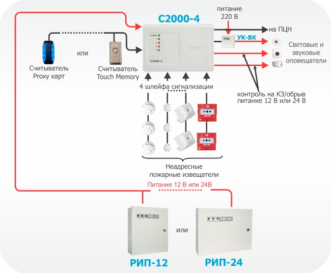
Figure 1. Autonomous use of the S2000-4 device
"S2000-4" is used in autonomous mode at small sites. For example, the device can be used in small shops, small offices, apartments, etc.
The device has:
- Four alarm loops, which can include any type of non-addressable fire detectors. All loops are freely programmable, i.e. for any loop, you can set types 1, 2, 3, and also configure other configuration parameters individually for each loop.
- Two relay outputs of the “dry contact” type and two outputs with monitoring of the health of connection circuits. You can connect actuators (light and sound alarms) to the relay outputs of the device, and also transmit notifications to the monitoring station using a relay. In the second case, the relay output of the object device is included in the so-called “general alarm” loop of the notification transmission device, which has a built-in transmitter via the GSM channel and/or an output for connection to the GTS. Thus, when the device switches to the “Fire” mode, the relay closes, the general alarm loop is broken and an alarm notification is transmitted to the monitoring station via GSM channels or via the telephone network;
- Circuit for connecting a reader (you can connect various readers operating via the TouchMemory, Wiegand, AbaTrackII interface).
- Four indicators of the status of alarm loops, as well as an indicator of the operating mode of the device.
Control Panel Signal-10
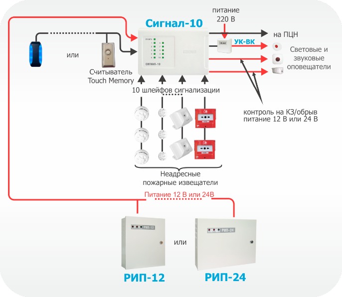
Figure 2. Autonomous use of the Signal-10 device
"Signal-10" is used in autonomous mode at small and medium-sized facilities.
The device has a convenient function for controlling the state of zones using contactless identifiers - Touch keys Memory or Wiegand (up to 85 user passwords). The powers of each key can be flexibly configured - to allow full control of one or an arbitrary group of loops, or to allow only the transfer of loops. The powers of each key can be flexibly configured - to allow full control of one or an arbitrary group of loops, or to allow only the transfer of loops.
The device has:
1. Ten alarm loops, which can include any types of non-addressable fire detectors. All loops are freely programmable, i.e. for any loop you can set types 1, 2 and 3, and also configure other configuration parameters individually for each loop.
2. Two relay outputs of the “dry contact” type and two outputs with monitoring of the health of connection circuits. You can connect actuators (light and sound alarms) to the relay outputs of the device, and also transmit notifications to the monitoring station using a relay. In the second case, the relay output of the object device is included in the so-called “general alarm” loop of the notification transmission device, which has a built-in transmitter via the GSM channel and/or an output for connection to the GTS. Thus, when the device switches to the “Fire” mode, the relay closes, the general alarm loop is broken and an alarm notification is transmitted to the monitoring station via GSM channels or via the telephone network.
3. A circuit for connecting a reader, which provides a convenient way to control arming and disarming using electronic keys or cards. You can connect any Touch Memory key readers or contactless Proxy cards that have a Touch Memory interface at the output (for example, “Reader-2”, “S2000-Proxy”, “Proxy-2A”, “Proxy-3A”, etc. ).
4. Ten indicators of the status of alarm loops and a functional indicator of the device’s operation.
Control Panel Signal-20M
"Signal-20M" can be used in small and medium-sized facilities (for example, warehouses, small offices, residential buildings etc.).
To control the state of zones, PIN codes can be used (64 user PIN codes are supported). User permissions (for each PIN code) can be flexibly configured - to allow full control, or to allow only re-arming. Any user can manage an arbitrary number of loops; for each loop, arming and disarming powers can also be individually configured.
Twenty alarm loops of "Signal-20m" provide sufficient localization of the alarm notification at the mentioned objects when any security detector in the train. The device has:
1. Twenty alarm loops, which can include any types of non-addressable fire detectors. All loops are freely programmable, i.e. for any loop you can set types 1, 2 and 3, and also configure other configuration parameters individually for each loop;
2. Three relay outputs of the “dry contact” type and two outputs with monitoring of the health of connection circuits. You can connect actuators (light and sound alarms) to the relay outputs of the device, and also transmit notifications to the monitoring station using a relay. In the second case, the relay object output of the device is included in the so-called “general alarm” loop of the notification transmission device, which has a built-in transmitter via the GSM channel and/or an output for connecting to the GTS. The operating tactics for the relay are determined, for example, turn on during an alarm. Thus, when the device switches to the “Fire” mode, the relay closes, the general alarm loop is broken and an alarm notification is transmitted to the monitoring station via GSM channels or via the telephone network;
3. Keyboard for controlling the state of zones on the device body using PIN codes. The device supports up to 64 user passwords, 1 operator password, 1 administrator password. Users can have rights either to arm and disarm alarm loops, or only to arm, or only to remove. Using the operator password, it is possible to put the device into test mode, and using the administrator password, enter new user passwords and change or delete old ones.
4. Twenty alarm loop status indicators, five output status indicators and functional indicators “Operation”, “Fire”, “Fault”, “Alarm”.
Figure 3. Autonomous use of Signal-20M
Non-addressed fire alarm system in ISO ORION
Figure 4 shows an example of organizing a non-addressed fire alarm system using ISO Orion devices. It is possible to connect threshold fire sensors to each of the devices various types(smoke, heat, flame, manual). The alarm loops of each device are freely programmable, i.e. for any loop, you can set types 1, 2 and 3, and also configure other configuration parameters individually for each loop. Each device has relay outputs, with which you can control various actuators - light and sound alarms, as well as transmit an alarm signal to the central monitoring console. For the same purposes, you can use the S2000-KPB control and launch unit. Additionally, the system is equipped with a “S2000-BI” display unit, which is designed to display the status of instrument zones at the observation post. Control of the state of zones, as well as viewing of system events, is carried out from the network controller - the “S2000-M” remote control. Often the remote control is also used to expand the fire alarm system - to connect additional control panels or relay modules. That is, to increase the performance of the system and its expansion. Moreover, the expansion of the system occurs without its structural changes, but only by adding new devices to it.
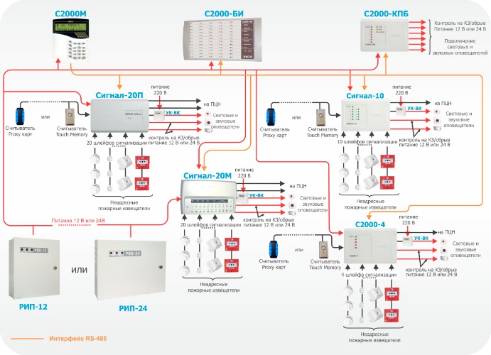
Figure 4. Non-addressable fire alarm system
Addressable threshold fire alarm system using ISO Orion devices
To build an address-threshold fire alarm system in ISO "Orion" the following are used:
- Reception and control device "Signal-10" with address-threshold mode of alarm loops
- Smoke optical-electronic threshold-addressable detector "DIP-34PA"
- Thermal maximum-differential threshold-addressable detector "S2000-IP-PA"
- Manual threshold-addressable detector “IPR 513-3PA”
When connecting the specified detectors to the “Signal-10” device, the device loops must be assigned type 14 - “Fire addressable-threshold”. Up to 10 addressable detectors can be connected to one addressable threshold loop, each of which is capable of reporting its current status upon request of the device. The device periodically polls addressable detectors, monitoring their performance and identifying a faulty or alarming detector. “Signal-10” accepts the following types of notifications from addressable detectors: “Normal”, “Dusty, maintenance required”, “Fault”, “Fire”, “Manual fire”, “Test”, “Shutdown”. Each addressable detector is considered as an additional addressable zone of the device. When the device operates in conjunction with a network controller, each addressable zone can be disarmed and armed. When arming or disarming a threshold-addressable loop, those address zones that belong to the loop are automatically removed or taken. In this case, addressable zones that are not associated with a loop do not change their state when a threshold-addressable loop is taken or removed.
When setting up the Signal-10 device, it is possible to pre-specify the addresses of those detectors that will be included in the threshold-addressable loop. To do this, use the “Initial linking of AL to addresses” parameter. If there is no binding of the detector address zone to the loop, this zone does not participate in the formation of the generalized state of the loop; commands when arming/disarming the loop are not applied to it.
The addressable threshold loop can be in the following states (states are given in order of priority):
- “Fire” - at least one addressable zone is in the “Manual fire” state, two or more addressable zones are in the “Fire” state, or the alarm/fire delay has expired;
- “Attention” - at least one address zone is in the “Fire” state;
- “Fault” - one of the addressable zones is in the “Fault” state;
- “Disabled” - one of the address zones is in the “Disabled” state;
- “Non-arming” - at the moment of arming, the addressable zone is in a state different from the “Normal” state;
- “Dusty, maintenance required” - one of the address zones is in the “Dusty” state;
- “Disarmed” (“Disarmed”) – one of the address zones is disarmed;
- “On guard” (“Armed”) – all addressable zones are normal and armed.
If the “Fire” state of one addressable zone is detected in the addressable threshold loop, the loop goes into the “Attention” state. If the “Manual fire” or “Fire” state is detected for two addressable zones, the loop goes into the “Fire” mode. The transition from the “Attention” mode to the “Fire” mode is also possible by a timeout equal to the value of the “Fire transition delay” parameter. If the value of the “Fire transition delay” parameter is equal to zero, the loop switches to the “Fire” mode when one automatic addressable detector. If the “Fire transition delay” value is 255 (infinite delay), the loop switches to the “Fire” mode only when two automatic addressable detectors or one manual detector are triggered.
If the device does not receive a response from the detector within 10 seconds, its address zone is assigned the “Disabled” status. In this case, there is no need to use a cable break when removing the detector from the socket, and the functionality of all other detectors is maintained. A threshold-addressable loop does not require an end-of-line resistor, and an arbitrary loop topology can be used: bus, ring, star, or any combination of them.
When organizing an address-threshold system burglar alarm To operate the outputs, you can use operating tactics similar to those used in the non-address system (see above). Figure 5 shows an example of organizing an address-threshold fire alarm system using the Signal-10 device.
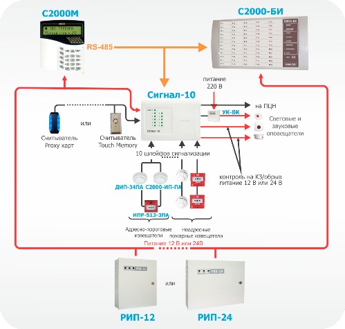
Figure 5. Address-threshold PS using Signal-10
Addressable analogue fire alarm system using ISO Orion devices
Addressable analogue fire alarm system in ISO "Orion" is built using the following devices:
- Controller of two-wire communication line “S2000-KDL”;
- Fire smoke optical-electronic addressable analogue detector “DIP-34A”;
- Firefighter thermal maximum-differential addressable analog "S2000-IP"
- Fire manual addressable call point “IPR 513-3A”
- Branching and insulating blocks "BREEZ", "BREEZ" used. 01. The devices are designed to isolate short-circuited areas with subsequent automatic recovery after the short circuit is removed. "BREEZE" is installed in the line as a separate device, "BREEZE" is used. 01 is built into the base of fire detectors “S2000-IP” and “DIP-34A”
- Address extenders “S2000-AR1”, “S2000-AR2”, “S2000-AR8”. The devices are designed for connecting non-addressable four-wire detectors. Thus, conventional threshold detectors can be connected to the addressable system.
The two-wire communication line controller actually has one signaling loop to which up to 127 addressable devices can be connected. Addressable devices can be fire detectors, addressable expanders or relay modules. Each addressable device occupies one address in the controller memory. Address extenders occupy as many addresses in the controller’s memory as loops can be connected to them (“S2000-AP1” - 1 address, “S2000-AP2” - 2 addresses, “S2000-AP8 – 8 addresses). Addressable relay modules also occupy 2 addresses in the controller memory. Thus, the number of protected premises is determined by the addressable capacity of the controller. For example, with one “S2000-KDL” you can use 127 smoke detectors, or 17 smoke detectors and 60 addressable relay modules. When addressable detectors are triggered or when addressable expander loops are disrupted, the controller issues an alarm notification via the RS-485 interface to the S2000M control panel.
For each addressable device in the controller, a zone type must be specified. The zone type indicates to the controller the tactics of the zone and the class of detectors included in the zone.
Type 2 – “Combined firefighter”. A zone of this type includes addressable expanders with threshold detectors included in them. . In this case, the addressable expanders will recognize such conditions as “Normal”, “Fire”, “Open” and “Short circuit”.
Type 3. Fire thermal. A zone of this type can include addressable fire manual call points “IPR-513-3A”, as well as addressable expanders with threshold detectors included in them. You can also include the S2000-IP detector in a zone of this type, but in this case the detector loses its analog qualities.
Possible zone states:
- “Taken” – the zone is completely controlled;
- “Disabled” – the zone is normal if there are no faults;
- “Failure to arm” – the controlled parameter of the control system was not normal at the time of arming;
- “Arming delay” – the zone is in the arming delay state;
- “Fire” – the addressable heat detector has detected a change or excess of the temperature value corresponding to the condition for switching to the “Fire” mode (maximum differential mode); address manual call point transferred to the "Fire" state (glass breaking). For addressable expander loops, there are certain loop resistance values corresponding to this state;
- “Short circuit” – For addressable expander loops, there are certain loop resistance values corresponding to this condition;
- “Fire equipment malfunction” – the measuring channel of the addressable heat detector is faulty.
Type 8. Smoke analogue addressable. This type of zone can include fire smoke optical-electronic addressable analogue detectors “DIP-34A”. In standby mode, the controller requests numerical values corresponding to the level of smoke concentration measured by the detector. Pre-warning thresholds are set for each zone "Attention" and alerts "Fire". Trigger thresholds are set separately for time zones "NIGHT" And "DAY".
Periodically, the controller requests the dust content value of the smoke chamber, the resulting value is compared with the threshold "Dusty", set separately for each zone.
Possible zone states:
- “Taken” – the zone is controlled, the thresholds “Fire”, “Attention” and “Dusty” are not exceeded;
- “Removed” – only the “Dusty” threshold and faults are monitored;
- “Fire equipment malfunction” – the measuring channel of the addressable detector is faulty;
- “Service required” – the internal threshold for automatic compensation of dust content in the smoke chamber of the addressable detector or the “Dusty” threshold has been exceeded.
Type 9. “Thermal addressable analog”. A zone of this type can include fire thermal maximum-differential addressable analogue detectors “S2000-IP”. In standby mode, the controller requests numerical values corresponding to the temperature measured by the detector. Pre-warning temperature thresholds are set for each zone "Attention" and alerts "Fire".
Possible zone states:
- “Taken” – the zone is controlled, the “Fire” and “Attention” thresholds are not exceeded;
- “Cleared” – only faults are monitored;
- “Arming delay” – the zone is in the arming delay state;
- “Failure to arm” – at the time of arming, one of the “Fire”, “Attention” or “Dusty” thresholds has been exceeded or a malfunction is present;
- “Attention” – the “Attention” threshold has been exceeded;
- “Fire” – the “Fire” threshold has been exceeded;
- “Fire equipment malfunction” – the measuring channel of the addressable detector is faulty.
You can also configure additional parameters for loops:
- Automatic re-arming from alarm - allows automatic transition from the “Alarm”, “Fire” and “Attention” states to the “Armed” state when the zone violation is restored. In this case, in order to transition to the “Armed” state, the zone must be normal for a time no less than that specified by the “Recovery time” parameter.
- Without the right to disarm – serves to allow the zone to be constantly monitored, that is, a zone with this parameter cannot be disarmed under any circumstances.
When organizing an addressable analogue fire alarm system, “S2000-SP2” devices can be used as relay modules. These are addressable relay modules, which are also connected to the S2000-KDL via a two-wire communication line.
For the S2000-SP2 relay, you can use operating tactics similar to those used in the non-addressable system (see above).
The S2000-KDL controller also has a circuit for connecting readers. You can connect various readers operating via the Touch Memory or Wiegand interface. From the readers it is possible to control the state of the controller zones. In addition, the device has functional indicators of the operating mode status, DPLS lines and an exchange indicator via the RS-485 interface. Figure 6 shows an example of organizing an addressable analogue fire alarm system under the control of the S2000M remote control.
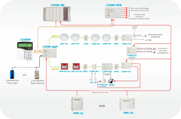
Figure 6. Addressable analogue fire alarm system using "S2000-KDL"
Explosion-proof solutions based on addressable analogue fire alarm system
If it is necessary to equip a fire alarm for an object with explosive zones, together with an addressable analogue system built on the basis of the S2000-KDL controller, it is possible to use intrinsically safe barriers "BRShS-ex" (Figure 7).
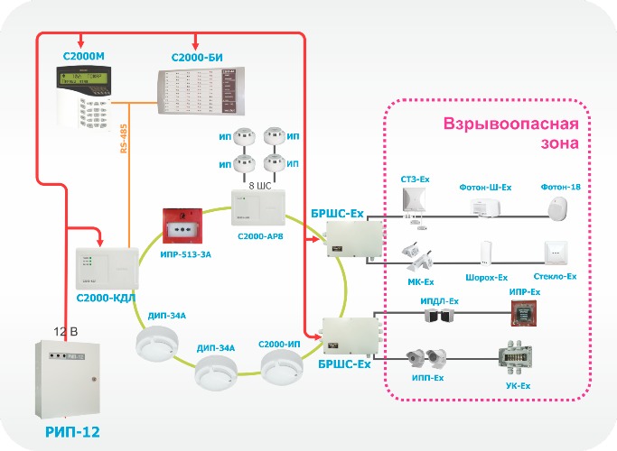
Figure 7. Explosion-proof solutions based on the addressable analogue PS system
This unit provides protection at the level of an intrinsically safe electrical circuit. This method of protection is based on the principle of limiting the maximum energy accumulated or released by an electrical circuit in emergency mode, or dissipating power to a level significantly below the minimum energy or ignition temperature. That is, the voltage and current values that can enter the danger zone in the event of a malfunction are limited. The intrinsic safety of the unit is ensured by galvanic isolation and the appropriate selection of the values of electrical clearances and creepage paths between intrinsically safe and associated intrinsically hazardous circuits, limiting voltage and current to intrinsically safe values in the output circuits through the use of compound-filled spark protection barriers on zener diodes and current-limiting devices, ensuring electrical clearances, leakage paths and integrity of spark protection elements, including due to their sealing (filling) with a compound.
BRShS provides:
- receiving notifications from connected detectors via two intrinsically safe loops by monitoring their resistance values;
- power supply external devices from two built-in intrinsically safe power supplies;
- relaying alarm messages to the two-wire communication line controller.
The X sign after the explosion protection marking means that only explosion-proof electrical equipment with the type of explosion protection “intrinsically safe electrical circuit i”, which has a certificate of conformity and a permit for use, is allowed to be connected to the connecting devices “BRShS-Ex” marked “intrinsically safe circuits”. Federal service on environmental, technological and nuclear supervision in explosive areas. The BRHS occupies two addresses in the address space of the S2000-KDL controller.
It is possible to connect any threshold detectors of special design to “BRSHS-Ex”. Today, the company ZAO NVP "Bolid" supplies a number of sensors for installation inside an explosive zone (explosion-proof version):
- Foton-18 – security passive optical-electronic detector;
- Foton-Sh-Ex – security infrared passive optical-electronic “curtain” detector;
- Steklo-Ex – security acoustic detector;
- Shorokh-Ex – security surface vibration detector;
- MK-Ex – security magnetic contact detector;
- STZ-Ex – flood alarm;
- IPD-Ex – optical-electronic smoke detector;
- IPDL-Ex - smoke optical-electronic linear detector;
- IPP-Ex – infrared detector flame;
- IPR-Ex - manual call point
Additional capabilities of the PS when using the software
In some cases, when building a fire alarm system, a personal computer with a specialized pre-installed device is used. software. The software can expand the functionality of the S2000M remote control, namely, it can be used to organize an automated workstation of the control post, keep a log of events and alarms, indicate the causes of alarms, collect statistics on addressable fire detectors, as well as build various reports.
To organize automated workstations in ISO "Orion", the following software can be used: automated workplace "S2000", automated workplace "Orion PRO".
AWP "S2000" allows you to implement the simplest functionality - monitoring system events. This software can be used if it is necessary to monitor several autonomous devices from an observation post and log events. In this case, the fire alarm is controlled directly from the control elements of the devices (“Signal-20M”) or from the readers (“S2000-4”, “Signal-10”).
PCs with Orion PRO workstation allow you to implement the following functions:
- Accumulation of OS events in the database (based on PS alarms, operator reactions to these alarms, etc.);
- Creating a database for a protected object - adding loops, sections, relays to it, arranging them on floor plans;
- Creating access rights to manage PS objects (loops, sections), assigning them to duty operators;
- Placement of logical substation objects (loops, partition areas, relays) on graphic floor plans of premises
- Interrogation and control of control and control devices connected to a PC, including remote controls. That is, from a computer you can simultaneously interrogate and control several subsystems, each of which operates under the control of a remote control;
- Setting up automatic system reactions to various events;
- Displaying the state of the protected object on graphic plans of premises, managing logical PS objects (loops, sections);
- Registration and processing of fire alarms occurring in the system, indicating the reasons, service marks, as well as their archiving;
- Providing information about the state of PS objects in the form of an object card;
- Generating and issuing reports on various PS events;
- Camera display CCTV, as well as managing the state of these cameras.
Physically, a computer with software is connected to the Orion ISO through an interface converter, one at a time, and the options shown in Figure 8. The number of workstations that can be simultaneously used in the system (Workstation software modules) is also shown here.
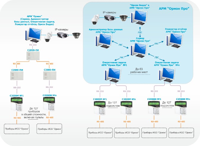
Figure 8. Connecting the workstation to ISO Orion devices
The assignment of automatic fire alarm tasks to software modules is shown in Figure 9. It is worth noting that the Orion ISO devices interact with the system computer on which the “Operational Task” software module is installed. Software modules can be installed on computers in any way - each module on a separate computer, a combination of any modules on a computer, or installing all modules on one computer.

Figure 9. Software module functionality
The Instructions for Signaling on Industrial Railway Transport establishes a system of sound signals for transmitting orders and instructions related to the movement of trains and shunting work.
Signals serve to ensure traffic safety, as well as to clearly organize train movement and shunting work.
Combination of sounds of different durations
Sound signals trains are expressed by the number and combination of sounds of varying duration:
During maneuvers sound signals are used:
forward: one long sound.
The locomotive is allowed to follow the control back: two long sounds.
Sound signals during maneuvers are given by a hand whistle or a blow horn.
Signals during maneuvers must be repeated by the locomotive's whistles, confirming their acceptance for execution.
Sound signals when moving trains
Three short "Stop"
One long one - “Go to the train
Three long and one short - - - “The arrival of the train at the station is not full
Following double traction:
One short Requirement for the driver of the second locomotive to “reduce traction”
Two short Requests for the driver of the second locomotive to “increase traction”
Two long and two short - - Requirement “Lower the pantograph.
Sound signals when trains move with pushing locomotive:
Two short demands to "start pushing"
- the driver repeats the signal pushing
One short, one long and one short - Demand to "stop pushing, but keep up with the train"
Four long - - - - Demand to “stop pushing and go back
When a double traction train is traveling with a pushing locomotive, the driver of the second locomotive repeats all the signals after they are given from the pushing locomotive.
Alert signal served as one long whistle- in cases:
approach of the train to stations (posts), portable and manual signals requiring a reduction in speed, signal signs "C", excavations, curved sections of the track, tunnels;
when meeting trains on sections: the first signal - when approaching an oncoming train, the second - when approaching the tail section;
when approaching people on the track and in other cases requiring notification of the approach of a train.
Alert signal served one short and one long whistle locomotive
- and repeats periodically:
when following a traffic light with a red light, as well as with an unclear indication or one that has gone out, after parking in front of it and when further following the block section;
when approaching the entrance traffic light with a moon-white flashing light of the invitation signal and in all other cases of receiving a train at the station with a prohibitory indication or the main lights of the entrance traffic light have gone out;
when receiving a train on the wrong track (in the absence of an entrance traffic light on this track). This signal must also be given when further following the neck of the station;
when approaching a traffic light with a red light, which has a conditionally permitting signal, and further following the block section.
Alarms are given by locomotive whistles, sirens, and blows to suspended metal objects.
The signal "General alarm is given" groups of one long and three short sounds:
- - -
when a malfunction is detected along the route that threatens traffic safety;
when a train stops in a snow drift, when a train ruptures, a train crash and in other cases when assistance is required.
The fire alarm signal is given in groups of one long and two short sounds:
- - -
The general and fire alarm signals are given, if necessary, by each railway worker.
The meaning of sound signals is the same day and night.
an alarm signal to notify of a fire or any other disaster, sounded by bells; trans. Intensely draw public attention to any danger; raise the alarm
Alternative descriptionsAlarm bell ringing
Ringing the bell as a signal to gather people in case of fire or alarm
Story by L. Tolstoy
. "SOS!" from the bell tower
. "Alarm" from the bell ringer
SOS from the bell ringer
Restless ringing of the bell
Ring the bells
Bells chime
A large brass drum carried by horses and used to give a general alarm to troops
Buchenwald...
IN Ancient Rus' one could see a huge military drum being transported on four horses, and what was it called?
Flash, frequent random ringing of a large bell, fire alarm, etc.
Bells ringing
Fire call
Public sound ringing
Danger ringing
The bell that rings the alarm
Bell tower anxiety
Bell "shot"
Bell siren
Alarm bell
Bell "SOS!"
Bell "ATAS"
Bell sound during a fire
Bell analogue of a fire siren
Bell ringing
Frequent bell ringing, alarm signal
The ringing of bells that worries people more than the fall of the ruble
Ringing bells indicating alarm
Bell commotion
Distress bell
M. agitation, commotion, anxiety; beating a drum, beating a board, ringing bells, rattling a rattle, to gather people, on the occasion of a fire or other general danger. Sound the alarm or sound the alarm. Alarm, alert, related to the alarm. Call on the arch. sound, sound the alarm. Nabatchik m. nabatchitsa w. who will sound the alarm
Call back in case of emergency
Fire siren played by bells
Predecessor of the fire siren
Story by L. N. Tolstoy
A story by Russian writer L. Andreev
Novel by L. N. Tolstoy
Russian drum musical instrument, type of timpani
Alarm signal from the bell tower
Since the times of Ancient Rus' - an alarm signal for gathering people, frequent random ringing of a large bell, notifying of a disaster, general danger
Hasty work on the ship
Alarm from the belfry
Alarm bells
Alarm from the bell tower
Alarming "beating" of bells
Alarm bell rings
Alarm bell
Alarm bells ringing
Alarm bell ringing
Alarm chime
Alarm signal
Ringing the bell
Ringing the bell as a signal to gather people in case of fire or alarm
The bells are ringing
An obsolete large drum that sounded the alarm in the army.
Church alarm
Alarm bells
Fire alarm bell
Flash, frequent random ringing of a large bell, fire alarm, etc.
In Ancient Rus' one could see a huge military drum being transported on four horses, but what was it called?
. "SOS!" from the bell tower
Alarming "beating" of bells
Bell sound during a fire
. "alarm" from the bell ringer
Bell "SOS!"
Bell "ATAS"
Bell "shot"
Bell analogue of a siren
Procedure in case of emergency
1. Signs of a starting fire
A fire most often begins with the appearance of a small flame, which is preceded by a more or less long period of heating or smoldering of combustible objects. A fire can occur either from the short circuit of live parts of electric heating, laboratory devices and office equipment, as well as as a result of overloading internal electrical networks, or from careless handling of fire. From the smoldering of the combustible material, smoke appears almost immediately - at first barely noticeable, and then the smoke becomes increasingly thicker. Spread of combustion products (smoke, carbon monoxide, soot), as well as fire, is preceded by free, uncontrolled combustion of flammable substances and drafts that occur when doors and windows are open. Fire spreads very quickly if it enters Fresh air, providing an additional supply of oxygen. This is why you should not break glass in the windows of a burning room and leave open doors to adjacent rooms.
The occurrence of a fire can be determined:
- when a sound signal is received Fire alarm and voice warning about fire.
- by the smell of smoke from smoldering and combustion products.
- by the crackling sound of burning wood or material.
2. Actions of teachers and students upon receiving a signal about a fire in an academic building
Regardless of where the fire occurred, when a sound signal about a fire and a duplicate voice signal notifying “Fire, please leave the premises” is received, the teacher must:
If there is or is no smoke in the corridor, the teacher must immediately decide on ways to evacuate students from the classroom. Having slightly opened the door leading to the common corridor, make sure that the escape routes are not cut off by fire and smoke.
Within 3-5 seconds, appoint a group leader or other person as the head of a group of evacuating students, while simultaneously indicating the path of the group along the main evacuation route, as well as indicating possible alternate evacuation routes in case of force majeure, and where the group should gather after leaving from the building.
Standing at the entrance to the classroom, control the evacuation of students in the direction that the teacher considered the safest for the life and health of students.
Monitor the complete evacuation of students from the premises. Physically weak students and students who have suffered psychological shock are assigned students who will provide assistance during evacuation.
Upon completion of the evacuation to a safe place, the teacher must make sure that the students have fully exited the building, and together with the group leader, conduct a roll call.
When driving, you must move calmly, do not overtake comrades walking ahead, do not create panic.
When leaving the building, the teacher must inform the shift of the educational building about the number of students who left the classroom and the room number.
3. Actions of teachers and students if it is impossible to evacuate the premises through a common corridor
After making sure that due to heavy smoke and high temperature Evacuation of students from the classroom is impossible:
Open the window and try to attract the attention of passers-by by shouting for help. When they hear you, they will call the fire department if others have not called it before.
Upon arrival of fire departments, it is necessary to evacuate students using a fire auto-mechanical ladder or a retractable three-leg ladder, as well as by jumping onto an inflatable trampoline.
The teacher is obliged to prevent students from jumping out of windows onto sidewalks and lawns, and to prevent panic among students.
The teacher bears full responsibility for the safety, preservation of life and health of students during classes.
4. Actions in case of fire detection
In the event of a fire in the initial stage of its development, the teacher and students are obliged to:
By phone 01 (from cell phone 010) report the fire to the fire department, giving the exact address, what is on fire and your last name. Report the occurrence of a fire to the operational duty officer of the university's emergency department (tel. 900-127) and to the watch of the academic building.
Take all possible measures to evacuate people and extinguish the fire.
5. Actions of students in the event of a fire in the dormitory
Almost all university dormitories are high-rise buildings and if a fire occurs in one of the dormitory premises, there may be a threat of cutting off individual premises (rooms) from evacuation routes. Therefore, the main actions for students in the event of a fire are:
Upon receiving the “Fire alarm” signal and the voice notification “Fire, everyone must leave the premises,” each student must take the necessary things, documents and evacuate from the dormitory. The main escape routes are internal stairs leading to the 1st floor level.
In the event of smoke or fire on the ground floor, evacuation is carried out via stairs and through emergency exits located at the rear of the building. Evacuation exits open automatically when the fire alarm is triggered.
If the fire was noticed late, fire and smoke blocked you in the room, you must:
Retard the spread of fire by closing doors tightly.
If possible, seal the gaps between door leaves and the floor with a cloth moistened with water. If possible, curtain the doors with a blanket.
Open the window and try to attract the attention of passers-by by shouting for help. When the room is filled with smoke, you can breathe through a wet cloth. Don't hide under beds or in closets - this will make it harder for firefighters to find you.
We must remember:
- that combustion products (carbon monoxide, smoke) are concentrated in the upper part of the room, therefore, at a height of 0.5 to 1.0 meters from the floor there is always a zone of clean air for breathing and by bending closer to the floor, you can always get out of the smoke-filled area.
- that recklessness in actions can lead to loss of life.