Orion: fire alarm as part of an integrated set of protective measures
13 GENERAL INFORMATION ABOUT INTEGRATED SECURITY SYSTEMS
13.1 Principles of organizing integrated security systems
13.1.1 Definition of an integrated security system
The security problem of any object requires a certain approach to be solved. Thus, to ensure the safety of small objects, it is usually sufficient to use technical means burglar alarm. At the same time, it is obvious that to solve the problem of security of objects, unauthorized entry into which can lead to particularly large or irreparable damage, a threat to health or life large quantity people, with the help of signaling devices alone is impossible. Therefore, in our country and abroad, they have become widely used in the protection of such objects. security systems, including, in addition to security alarm systems, television surveillance and access control equipment. The first complexes were, as a rule, a symbiosis of three independent, unrelated subsystems and could not solve the problem, since the tripled volume of information duplicated by each subsystem was practically impossible to process and did not allow the operator to make the right decision.
In this regard, in Lately An integrated approach to ensuring the security of important facilities has become generally accepted, one of the main directions of which is the creation of integrated security systems (ISO).
In the very general view the purpose of integration is to obtain ISO new functions while maintaining the full capabilities of its individual components, saving the funds necessary to implement these functions, maximum automation of actions in all areas of object protection. The information is provided to the operator after analysis and processing in the system itself, which makes it possible to increase its reliability and quickly make a decision in accordance with the situation that has arisen.
A formalized definition of ISO has not yet been fully developed, however, generalizing the opinions of experts, we can assume that integrated security system is a collection of united general management systems and means of security alarms, access control and/or video monitoring that have technical, information, software and operational compatibility and are designed to solve facility security problems.
The ISO, if necessary, may include other subsystems that ensure, for example, the normal functioning of life support systems, fire and information security and so on.
The technical means, individual subsystems, components, elements included in the ISO functionally intersect with each other to one degree or another and have, in addition to the general one, their own local control.
The controlling and obligatory element of any ISO is a security alarm subsystem. The remaining subsystems are designed to enhance the security of the facility and, depending on the requirements for its security level, may or may not be part of the ISO.
13.1.2 Structure and functions of the integrated security system
Most ISOs are built on the principle of two-level integration.
The first level is systemic. The central processor unites all ISO subsystems and ensures their interaction. Each of the subsystems automatically performs certain actions when a certain signal is received from any other.
The second level is modular. “Local” controllers control a small group of detectors, television cameras, readers, actuators, etc.
This construction of ISO has a number of advantages:
Thanks to its flexible architecture, the system can be easily constructed from a specific set of modules and blocks for almost any object;
During operation, it is quite simple to expand and improve the functions of the system by connecting various types recording and actuating devices.
ISOs are built on the basis computer technology and can be structurally divided into the following components:
Devices for receiving, transmitting and processing signals that allow you to receive the most complete information and recreate at the central security console a comprehensive and objective picture of the state of the premises and territory of the facility, the performance of equipment and equipment;
Actuating devices that can, if necessary, act automatically or at the command of an operator;
A control and management point (or points) for the information display system, through which operators can monitor the operation of the entire ISO;
The central processor, which visually represents and accumulates information for its subsequent processing;
Communications through which information is exchanged between ISO elements and operators.
This ISO structure provides them with the following functionality:
Control over a large number of premises and territories with the organization of several security lines;
Multi-level access for employees and visitors with a clear delineation of powers regarding the right of access to certain protected areas, by time of day and day of the week;
Identification of an object crossing a certain boundary;
Recognition of the intruder, allowing security personnel to take the most rational countermeasures;
Interaction between security posts and law enforcement agencies when providing security and in cases of localizing incidents;
Accumulation of documentary materials for use in the investigation and analysis of incidents.
In addition, the possibility of flexible programming of ISO and individual subsystems allows you to actively counteract such unauthorized actions as interrupting channels for transmitting alarm information; partial neutralization of the system by persons who have access to its individual elements and subsystems; destruction of information about the incident; violation by security personnel established order performing service, etc..
13.1.3 Selection of ISO characteristics for a specific object
The practical implementation of ISO at a specific facility poses a number of problems for developers and implementers, for example:
Determination of the main characteristics of ISO as a whole;
Determining the degree of integration;
Determining the intelligence level of the system to reduce negative influence human factor;
Selection of technical means;
Economic feasibility of the chosen option.
Despite the fact that there are already general approaches to organizing ISO, the solution to these problems remains purely individual. This is due not only to the size and architectural and planning features of the object, but, first of all, to the heterogeneity of protected areas in terms of required level security. Obviously, more stringent requirements are imposed on the equipment of a valuables storage facility than on the equipment of a regular office space. In this case, it is desirable to find a reasonable compromise between conceptual safety requirements and the real capabilities of existing technical means (for example, often a good result is obtained by using one subsystem to solve the functional problems of another subsystem, strengthening the role of the human factor, if further automation and saturation of the facility with technical means and systems is no longer possible gives a noticeable effect).
Recently, everything appears on the domestic security equipment market larger number suppliers of ready-made ISOs. This, on the one hand, simplifies, and on the other, complicates right choice systems for a specific object. Therefore, let us dwell on some basic points that make it easier to solve this complex problem.
First, the top-level issues are resolved as specifically as possible, with as much detail as possible: general issues relating to the site security strategy, reactions to possible violations, decision-making procedures and responsibility for them, etc.
The second stage is the selection of equipment according to the “cost - reliability” criterion. The following equipment can be recommended for ISO:
Equipment from well-known large companies (Sony, Panasonic, etc.). Typically this latest developments, high quality and whose reliability is guaranteed, as a rule, not so much by certificates as by a trademark. The cost of such equipment is very high;
Equipment from lesser-known companies with quality certificates. This is usually simple and relatively inexpensive equipment.
Cheap equipment, produced and sold for sale unknown by whom and how, which does not provide quality guarantees, should not be used.
When choosing equipment, you should pay attention not only to whether the system performs the functions you need, but also to ease of use, the procedure for warranty and post-warranty service, and the ability to quickly adapt the system to the changing functions of the facility using fairly simple methods.
Today, various integrated systems are used to create an appropriate level of security at a facility. Holistic protective complexes represent a set of technological means that serve to perform assigned tasks. Currently wide application receives a combination of burglar and fire alarms.
In practice, the Orion fire alarm system is integrated with the security subsystem.
The integrated Orion complex is presented as a set of technological, hardware and software specialized tools. Their work is aimed at identifying the facts of a fire, recording attempts of illegal access to the protected perimeter, conducting video surveillance, access control, switching on automatic systems warning and fire extinguishing. Such systems provide the opportunity to create dispatch services on their basis.
Tasks performed by integrated systems
Security fire alarm Orion is installed on a protected object to perform a number of tasks:
- Receiving, registering, processing, transmitting information coming from notification devices (security, fire, alarm);
- Access control and management access system(control of the operation of actuators, for example: turnstiles, barriers, gates, sluices, entrance doors etc.);
- Implementation of continuous internal and external video surveillance of the protected area;
- Regulation of the operation of automatic fire extinguishing and warning subsystems;
- Managing various engineering systems structures (including communications and air conditioning systems).
The Orion security alarm system in combination with the fire subsystem, due to its versatility, is designed to provide:
- The structure of the modules allows you to equip them with similar protective circuits objects of various scales;
- Low cost of installing one fire loop or checkpoint;
- An appropriate level of security for the created exchange protocols via communication channels between receiving devices and the control panel;
- Carrying out microprocessor analysis of incoming signals directly in installed loops;
- Measuring the resistance value to eliminate the occurrence of an emergency situation in the operation of the complex;
- Possibility of using various types of identifiers for access;
- Using keys to disarm or arm an object (these actions can also be carried out using a keyboard, control panel, or a combined method);
- Exercising comprehensive control over checkpoints;
- Management of the video surveillance subsystem and monitoring its operation;
- Registration of all emerging emergency situations in special protocols;
- Controlling the operation of subsystems against fire safety: fire extinguishing, warning, smoke removal, air conditioning.
What are the functional features of ISO?
Despite the fact that integrated systems are presented as an integral complex, each subsystem has its own characteristics. The work is performed both autonomously and through centralized control. The security alarm system as part of the integrated system has the following functional set:
- Autonomous monitoring of alarm and blocking contacts in one loop;
- Installation of protection on loops from outside interference;
- False alarm protection;
- Immunity from electrostatic and electromagnetic interference;
- Automatic reset of the alarm state when the object is armed;
- Variability of methods for arming and disarming an object;
- Creation of protocols containing information about ongoing events;
- Drawing up a graphic plan of the facility to display the performance and current state of all equipment;
- Programming access levels for workers and visitors;
- Differentiation of powers and access rights of administrators by installing a password system;
- Transmission of control commands to control and receiving mechanisms, actuators;
- Notification in case of an alarming situation with the ability to save transmitted messages;
- Processing alarm signals using a multi-stage principle;
- High level of system protection from installation and launch of unauthorized software or individual programs;
- Unlimited number of controlled zones within one section.
And the automatic fire extinguishing subsystem in the Orion complex is multifunctional. Among the main and auxiliary functions the following are distinguished:
- Possibility of recognizing repeated operation within one loop;
- Automatic reset of notification devices to eliminate the possibility of a false alarm;
- Connection of detectors of various types;
- Establishing and checking dust levels, temperature regime, smoke in the room;
- Organization of technical inspection of equipment and development of a list of measures to increase the degree of protection of the facility from fire;
- Graphic representation of the location of all notification devices;
- Keeping records of statistical data for the established reporting period;
- Programming of commands transmitted to the notification and automatic fire extinguishing subsystems;
- Installation of various types of fire extinguishing systems simultaneously;
- Monitoring the proper condition of several loops with checking the connecting circuits;
- Detection of broken connecting lines or short circuit;
- Transmitting commands to launch automatic fire extinguishing devices;
- Possibility of delaying the start of the launch automatic means extinguishing the flame;
- Remote control of the launch of fire extinguishing means by transmitting a command from the control panel;
- Manual launch of automatic installations;
- Automation of startup processes of fire extinguishing subsystems;
- Control technological devices premises;
- Automatic access blocking;
- Transmission of current messages and alarms to the “S2000” and “S2000-PT” consoles;
- Control of several fire pumps.
Also by their functional features the integrated complex has access control systems, video surveillance and control subsystems engineering structures building.
On the video - information about the security and fire alarm system:
Components of an integrated protection complex
The Orion IS includes a number of technical and software components:
- A hardware-software system equipped with specialized software, which includes automated workstations for the duty officer, the head of the security service, and those responsible for the video surveillance subsystem;
- Control panel (PKU “S 2000” and “S 2000 M”);
- LED keyboard type “S 2000-KS” and “S 2000-K”;
- Indicative block;
- Security and fire control and receiving mechanisms (Signal-20, 20M, 20P SMD, 20P SMD);
- A specialized controller that controls access to the facility;
- Electronic reader Touch keys Memory;
- Contactless ID readers;
- Signal and trigger block element.
In the case of installation of an address-type security and fire complex, the following equipment is installed:
- Signal and trigger block element “S 2000-SP1”;
- Two-wire controllers “S 2000-KDL”;
- Address extenders such as “S 2000-AR1”, “S 2000-AR2”, “S 2000-AR8”;
- Addressable notification mechanisms (surface and volumetric electro-optical, acoustic security, fire-smoke, magnetic contact, fire-thermal differentiated, manual fire detectors);
- Block branching and insulation elements;
- Reception and control mechanism for controlling installations of automatic fire extinguishing means of the “S 2000-ASPT” type;
- Fire control device type "Potok-3N";
- Indicative blocks;
- Interface converters of various types;
- Backup power supplies (12V and 24V).
All mechanisms, devices and devices that are part of the integrated complex scheme can be divided into six subgroups. The first subgroup includes devices that have radial loops. For example, the Signal-20 device and the like. They can work both offline and through centralized (network) control. The second subgroup of devices consists of notification transmission mechanisms. These include controllers, addressable detectors, signal and trigger block elements. Since all of the listed mechanisms are connected to the controller, its control can only be carried out using a network principle.
The third subgroup consists of mechanisms that ensure the performance of functions related to access control to the facility. These include controllers of the “S 2000-4” type with all subsequent modifications. Controllers can be used in network mode or to control access relative to a single point. The fourth subgroup of devices is formed by mechanisms for controlling the processing and transmission of information to external subsystems. Devices of this subgroup provide arming and disarming of an object. Thanks to these mechanisms, it is possible to monitor the current state of various sections of the subsystem and control execution devices.
The mechanisms that make up this subsystem do not work independently.
The fifth subgroup of elements includes devices and mechanisms for controlling automatic fire extinguishing installations. This subgroup is completed by devices of the “S 2000-ASPT” and “S 2000-KPB” types. The presence of these mechanisms makes it possible to construct a fire extinguishing scheme, smoke removal, and control of various engineering subsystems of the building in the event of an emergency. emergency. The sixth subgroup includes controllers and interface converters. Installed on personal computers software ARM Orion. These devices allow you to build a multi-level user interface and ensure its implementation according to different lines. If a complex complex in its structural set is installed at a facility, then a computer network can be used for control.
On the video there is more information about fire safety systems:
Alarm loops (inputs)
Depending on the type of connected detectors, when programming the configurations of Signal-10 blocks ver.1.10 and higher; "Signal-20P" ver.3.00 and higher; "Signal-20M" ver.2.00 and higher; "S2000-4" ver.3.50 and higher, inputs can be assigned one of the types:
Type 1 - Fire smoke two-threshold
The AL includes fire smoke detectors or any other normally open detectors. The unit can power detectors via a loop.
- “Disarmed” (“Disarmed”, “Disabled”) – the alarm loop is not controlled (can be used when servicing the system);
- “Attention” – the activation of one detector is recorded (with the “Blocking fire entry re-request” parameter enabled);
- “Fire 1” – the alarm goes into this state in the following cases:
- activation of one detector was confirmed (after re-query);
- the activation of two detectors was recorded (with the “Blocking fire entry re-request” parameter enabled) in one alarm loop for a time of no more than 120 s;
- The second transition to the “Attention” state of different inputs included in the same zone was recorded in a time of no more than 120 s. In this case, the input that switched to the “Attention” state first does not change its state;
- “Fire 2” – the alarm goes into this state in the following cases:
- the activation of two detectors (after a re-request) in one alarm zone was confirmed in a time of no more than 120 s;
- The second transition to the “Fire 1” state of different inputs entering the same zone was recorded in a time of no more than 120 s. In this case, the alarm system that switched to the “Fire 1” state first does not change its state;
- “Open” – loop resistance is more than 6 kOhm;
In general, when using smoke detectors, powered by the alarm loop, the parameter “Blocking fire input re-request” must be turned off. When the detector is triggered, the device generates an information message “Sensor triggered” and re-queries the alarm loop status: resets (short-term switches off) the alarm loop power supply for 3 seconds. After a delay equal to the value of the “Input analysis delay after reset” parameter, the device begins to evaluate the state of the loop. If within 55 seconds the detector is triggered again, the alarm goes into the “Fire 1” mode. If the detector does not trigger again within 55 seconds, the alarm loop returns to the “Armed” state. From the “Fire 1” mode, the AL can switch to the “Fire 2” mode in the cases described above.
The “Fire input re-request blocking” parameter is applied if the detector is powered from a separate source. Detectors with high current consumption (linear, some types of flame and CO detectors) are usually connected using this scheme. When the “Fire input re-request blocking” parameter is enabled, when the detector is triggered, the device generates an information message “Sensor triggered” and immediately switches the alarm loop to the “Attention” mode. From the “Attention” mode, the AL can switch to the “Fire 1” mode in the cases described above.
The alarm system includes fire smoke (normally open) and heat (normally closed) detectors. Possible modes (states) of AL:
- “On guard” (“Armed”) – the alarm system is controlled, the resistance is normal;
- “Arming delay” – the arming delay has not ended;
- “Attention” – the loop goes into this state in the following cases:
- a smoke detector was triggered (with the “Blocking fire entry re-request” parameter enabled)
- activation detected heat detector;
-
- smoke detector activation confirmed (after re-query);
- “Fire 2” – the alarm goes into this state in the following cases:
- the second transition to the “Fire 1” state was recorded for different alarm zones entering the same zone in a time of no more than 120 s. In this case, the alarm system that switched to the “Fire 1” state first does not change its state;
- “Short circuit” – loop resistance is less than 100 Ohms;
- “Failure to arm” – the alarm system was violated at the moment of arming.
When a heat detector is triggered, the unit goes into Attention mode. When a smoke detector is triggered, the unit generates the information message “Sensor Triggered.” When the “Blocking fire re-request” option is disabled. input” block performs a re-query of the alarm loop state (for more details, see type 1). If the activation of the smoke detector is confirmed, the AL switches to the “Fire 1” mode, otherwise it returns to the “Armed” mode. From the “Fire 1” mode, the AL can switch to the “Fire 2” mode in the cases described above. When the “Block re-request by fire” option is enabled. input”, the device immediately switches the AL to the “Attention” mode. From the “Attention” mode, the AL can switch to the “Fire 1” mode in the cases described above.
Fire thermal or any other normally closed detectors are included in the AL. Possible modes (states) of AL:
- “On guard” (“Armed”) – the alarm system is controlled, the resistance is normal;
- “Disarmed” (“Disarmed”, “Disabled”) – the alarm loop is not controlled;
- “Arming delay” – the arming delay has not ended;
- “Attention” – the activation of one detector is recorded;
- “Fire 1” – the alarm goes into this state in the following cases:
- the activation of two detectors in one alarm zone was recorded in a time of no more than 120 s;
- the second transition to the “Attention” state was recorded for different ALs included in the same zone in a time of no more than 120 s. In this case, the alarm system that switched to the “Attention” state first does not change its state;
- “Fire 2” – the alarm loop goes into this state if a second transition to the “Fire 1” state of different alarm loops belonging to the same zone is detected in a time of no more than 120 s. In this case, the alarm system that switched to the “Fire 1” state first does not change its state;
- “Short circuit” – loop resistance is less than 2 kOhm;
- “Open” – loop resistance is more than 25 kOhm;
- “Failure to arm” – the alarm system was violated at the moment of arming.
Type 16 – Firefighter manual.
Addressless manual (normally closed and normally open) fire detectors are included in the AL. Possible modes (states) of AL:
- “On guard” (“Armed”) – the alarm system is controlled, the resistance is normal;
- “Disarmed” (“Disarmed”, “Disabled”) – the alarm loop is not controlled;
- “Arming delay” – the arming delay has not ended;
- “Fire 2” – a manual call point has been detected;
- “Short circuit” – loop resistance is less than 100 Ohms;
- “Open” – loop resistance is more than 16 kOhm;
- “Failure to arm” – the alarm system was violated at the moment of arming.
When manual fire call points are triggered, the unit immediately generates a “Fire2” event, through which the “S2000M” remote control can send a command to control the systems fire automatics.
- "Arm Delay" defines the time (in seconds) after which the device attempts to arm the alarm system after receiving the corresponding command. Non-zero “Arming Delay” in fire alarm systems is usually used if, before arming the alarm system, it is necessary to turn on the device output, for example, to reset the power supply to 4-wire detectors (relay control program “Turn on for a while before arming”).
- "Input analysis delay after reset" for any type of loop, this is the duration of the pause before starting the analysis of the loop after its power is restored. This delay allows you to include detectors with big time readiness (time of “calm down”). For such detectors, it is necessary to set the “Input analysis delay after reset”, slightly exceeding the maximum readiness time. The unit automatically resets (turns off for 3 s) the power supply to the alarm loop if, when arming this loop, its resistance turned out to be less than normal, for example, a smoke fire detector in the alarm loop was triggered.
- “Without the right to disarm” does not allow you to disarm the alarm system in any way. This parameter is usually set for fire alarms to avoid their accidental removal.
- "Auto-receive from non-receipt" instructs the device to automatically arm an unarmed alarm as soon as its resistance is normal within 1 s.
AL devices and units “Signal-20M” ver.1.03, “Signal-20P” ver.2.05 and “S2000-4” ver.3.01 operate according to the following algorithms:
Type 1. Fire smoke with double trigger recognition.
The AL includes fire smoke detectors or any other normally open detectors. Possible modes (states) of AL:
- “Disarmed” (“Disarmed”) - the alarm loop is not controlled (used when servicing the system);
- “Arming delay” – the arming delay has not ended;
- “Open” - loop resistance is more than 6 kOhm;
When the detector is triggered, the device generates the message “Sensor Triggered” and re-queries the alarm loop state: it resets (short-term switches off) the loop power supply for 3 s. If within 55 seconds after the reset the detector is triggered again, the alarm loop switches to the “Attention” mode. If the detector does not trigger again within 55 s, the alarm loop returns to the “Armed” state. From the “Attention” mode, the AL can switch to the “Fire” mode if the second detector in this AL is triggered, as well as after the time delay specified by the “Transition to Alarm/Fire Delay” parameter has expired. If the “Transition to Alarm/Fire Delay” parameter is equal to 0, then the transition from the “Attention” mode to the “Fire” mode will occur instantly. The value of the “Transition to Alarm/Fire Delay” parameter, equal to 255 s (the maximum possible value), corresponds to an infinite time delay, and the transition from the “Attention” mode to the “Fire” mode is possible only when the second detector in the alarm loop is triggered.
Type 2. Firefighter combined single-threshold
The AL includes fire smoke and heat detectors or any other normally open and normally closed detectors. Possible modes (states) of AL:
- “On guard” (“Armed”) – the alarm system is controlled, the resistance is normal;
- “Disarmed” (“Disarmed”) – the alarm loop is not controlled (used when servicing the system);
- “Attention” – a heat detector has been triggered or a smoke detector has been triggered again;
- “Fire” - after the detector is triggered, the “Delay for transition to Alarm/Fire” has expired;
- “Short circuit” - loop resistance is less than 100 Ohms;
- “Break” - loop resistance is more than 16 kOhm (more than 50 kOhm for “S2000-4”);
- “Failure to arm” - the alarm system was violated at the moment of arming.
When the heat detector is triggered, the device switches to the “Attention” mode. When a smoke detector is triggered, the device generates a message “Sensor Triggered” and re-queries the AL status (see type 1). When the detector is confirmed to be triggered, the AL switches to the “Attention” mode.
From the “Attention” mode, the AL can switch to the “Fire” mode after the time delay specified by the “Transition to Alarm/Fire Delay” parameter has expired. If the “Transition to Alarm/Fire Delay” parameter is equal to 0, then the transition from the “Attention” mode to the “Fire” mode will occur instantly. The value of the “Transition to Alarm/Fire Delay” parameter, equal to 255 s (the maximum possible value), corresponds to an infinite time delay, and transition from the “Attention” mode to the “Fire” mode is impossible.
Type 3. Fireman's thermal two-threshold
Fire thermal or any other normally closed detectors are included in the AL.
Possible modes (states) of AL:
- “On guard” (“Armed”) - the alarm system is controlled, the resistance is normal;
- “Disarmed” (“Disarmed”) - the alarm loop is not controlled (used when servicing the system);
- “Arming delay” - the arming delay has not ended;
- “Attention” - the activation of one detector is recorded;
- “Fire” - more than one detector has been triggered, or after one detector has triggered, the “Transition to Alarm/Fire Delay” has expired;
- “Short circuit” - loop resistance is less than 2 kOhm;
- “Break” - loop resistance is more than 25 kOhm (more than 50 kOhm for “S2000-4”);
- “Failure to arm” - the alarm system was violated at the moment of arming.
When the detector is triggered, the device switches to the “Attention” mode for this alarm loop. From the “Attention” mode, the device can switch to the “Fire” mode if the second detector in the alarm loop is triggered, as well as after the time delay specified by the “Transition to Alarm/Fire Delay” parameter has expired. If the “Transition to Alarm/Fire Delay” parameter is equal to 0, then the transition from the “Attention” mode to the “Fire” mode will occur instantly. The value of the “Transition to Alarm/Fire Delay” parameter, equal to 255 s (the maximum possible value), corresponds to an infinite time delay, and a transition from the “Attention” mode to the “Fire” mode is possible only when the second detector in this alarm zone is triggered.
For each loop, in addition to the type, you can configure additional parameters such as:
- “Transition delay to Alarm/Fire” - for any of the fire loops this is the time of transition from the “Attention” state to the “Fire” state. Loops of type 1 and type 3 (with double trigger recognition) can also go into the “Fire” state when the second fire detector in the alarm loop is triggered. If the “Transition delay to Alarm/Fire” is 255 s, then the device does not switch to the “Fire” mode in time (infinite delay). In this case, loops of types 1 and 3 can go into the “Fire” state only when the second detector in the loop is triggered, and loop type 2 will not go into the “Fire” state under any conditions;
- “Local loop analysis delay after power reset” is the duration of the pause before loop analysis after removing the loop supply voltage (when re-querying the state of the fire loop and when arming). This delay makes it possible to include detectors with a long readiness time (calm-down time) in the loop;
- “Without the right to disarm” - does not allow the loop to be disarmed under any conditions;
- “Auto arming from Alarm/Fire” - the loop will automatically switch to the “Armed” state as soon as the loop resistance is normal for a time equal to the numerical value of this parameter multiplied by 15 s.
Events "Fire" PPKP "Signal-20M" ver.1.03 and BOD "Signal-20P" ver.2.05, "S2000-4" ver.3.01 from the point of view of the system correspond to the events "Fire 1". The listed devices themselves cannot generate “Fire 2” events. These events will be generated at the level of the S2000M console.
The maximum length of alarm loops is limited only by the resistance of the wires (no more than 100 Ohms).
The number of detectors included in one loop is calculated by the formula: N = Im / i, where: N is the number of detectors in the loop; Im – maximum load current: Im = 3 mA for AL types 1, 3, 16, Im = 1.2 mA for AL type 2; i – current consumed by the detector in standby mode, [mA]. The principles for connecting detectors are described in more detail in the operating instructions for the corresponding units.
Exits
Each BOD has relay outputs. Using the relay outputs of the devices, you can control various actuators, as well as transmit notifications to the monitoring station. The operating tactics of any relay output can be programmed, as well as the trigger binding (from a specific input or from a group of inputs).
When organizing a fire alarm system, the following relay operation algorithms can be used:
- Turn on/off if at least one of the loops associated with the relay has entered the “Fire 1”, “Fire 2” state;
- Turn on/off temporarily if at least one of the loops associated with the relay has entered the “Fire 1”, “Fire 2” state;
- Flash from the on/off state if at least one of the loops associated with the relay has switched to the “Fire 1”, “Fire 2” state;
- “Lamp” - blink if at least one of the loops connected to the relay has switched to the “Fire 1”, “Fire 2” state (blink with a different duty cycle if at least one of the connected loops has switched to the “Attention” state); turn on if the associated loop(s) are taken, turn off if the associated loop(s) are removed. In this case, anxiety states have higher priority;
- “Central monitoring station” - turn on when at least one of the loops connected to the relay is taken, in all other cases - turn off;
- “ASPT” - turn on for a specified time if two or more loops associated with the relay have switched to the “Fire 1” state or one loop to the “Fire 2” state and there is no violation of the technological loop. A broken technological loop blocks switching on. If the technological loop was violated during the relay control delay, then when it is restored, the output will be turned on for the specified time (violation of the technological loop suspends the counting of the relay activation delay;
- “Siren” - If at least one of the loops connected to the relay has switched to the “Fire 1”, “Fire 2” state, switch for a specified time with one duty cycle, if to the “Attention” state - with the other;
- “Fire monitoring station” - if at least one of the loops associated with the relay has entered the “Fire 1”, “Fire 2” or “Attention” state, then turn it on, otherwise turn it off;
- “Output “Fault” - if one of the loops associated with the relay is in the “Fault”, “Failure to Arm”, “Disarmed” or “Arm Delay” state, then turn it off, otherwise, turn it on;
- “Fire lamp” - If at least one of the loops associated with the relay has switched to the “Fire 1”, “Fire 2” state, then blink with one duty cycle, if in “Attention”, then blink with a different duty cycle if all associated with the relay the loops are in the “Armed” state, then turn them on, otherwise turn them off;
- “Old monitoring station tactics” - turn on if all the loops associated with the relay are taken or removed (there is no state “Fire 1”, “Fire 2”, “Fault”, “Failure”), otherwise turn off;
- Turn on/off for a specified time before taking the loop(s) associated with the relay;
- Turn on/off for a specified time when picking up a loop(s) associated with a relay;
- Turn on/off for a specified time when the loop(s) associated with the relay are not removed;
- Turn on/off when removing the loop(s) associated with the relay;
- Turn on/off when taking the loop(s) associated with the relay;
- “ASPT-1” - Turn on for a specified time if one of the loops associated with the relay has switched to the “Fire 1”, “Fire 2” state and there are no broken process loops. If the process loop was violated during the relay control delay, then when it is restored, the output will be turned on for the specified time (violation of the process loop suspends the counting of the relay activation delay);
- “ASPT-A” - Turn on for a specified time if two or more loops associated with the relay have gone into the “Fire 1” state or one alarm loop has gone into the “Fire 2” state and there are no broken process loops. A damaged process loop blocks switching on; when it is restored, the output will remain off;
- “ASPT-A1” - Turn on for a specified time if at least one of the loops associated with the relay has switched to the “Fire 1”, “Fire 2” state and there are no broken process loops. A damaged process loop blocks switching on; when it is restored, the output will remain switched off.
- At “Fire 2” turn it on/off for a while.
- When “Fire 2” blinks for a while from the OFF/ON state.
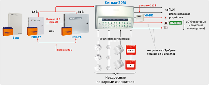
Signal-20M control panel in autonomous mode
"Signal-20M" can be used to protect small objects (for example, small offices, private houses, shops, small warehouses, industrial premises, etc.).
To control the inputs, the buttons on the front panel of the device can be used. Access to buttons is limited using pin codes (64 user pin codes are supported). User permissions (each PIN code) can be flexibly configured - allow full control, or allow only re-arming. Any user can manage an arbitrary number of loops; for each loop, arming and disarming powers can also be configured individually.
Twenty alarm loops of the Signal-20M device provide sufficient localization of the alarm notification at the mentioned objects when any fire detector in the loop is triggered.
The device has:
- Twenty alarm loops, which can include any type of non-addressable fire detectors. All loops are freely programmable, i.e. for any loop you can set types 1, 2 and 3, and also configure other configuration parameters individually for each loop;
- Three relay outputs of the dry contact type and two outputs with control circuit health monitoring. You can connect actuators to the relay outputs of the device, and also transmit notifications to the SPI using a relay. In the second case, the relay output of the object device is included in the so-called “general alarm” loops of the SPI terminal device. The operating tactics for the relay are determined, for example, turn on during an alarm. Thus, when the device switches to the “Fire 1” mode, the relay closes, the general alarm loop is broken and an alarm message is transmitted to the fire monitoring station;
- Keyboard for controlling the state of zones on the device body using PIN codes. The device supports up to 64 user passwords, 1 operator password, 1 administrator password. Users can have rights either to arm and disarm alarm loops, or only to arm, or only to remove. Using the operator password, it is possible to switch the device into test mode, and using the administrator password, enter new user passwords and change or delete old ones;
- Twenty alarm loop status indicators, five output status indicators and functional indicators “Operation”, “Fire”, “Fault”, “Alarm”.
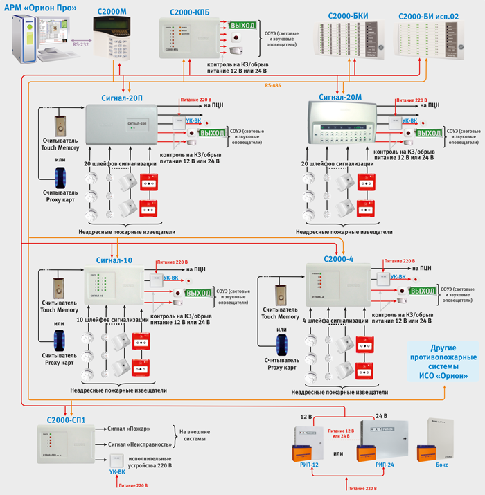
Block-modular PPKUP based on the S2000M remote control and BOD with non-addressable loops
As mentioned above, when constructing a block-modular control panel, the “S2000M” console performs the functions of indicating system states and events; organizing interaction between the components of the control panel (controlling display units, expanding the number of outputs, docking with SPI); manual control of inputs and outputs of controlled units. It is possible to connect threshold fire detectors of various types to each of the BODs. The inputs of each device are freely configurable, i.e. for any input you can set types 1, 2, 3 and 16, and assign other configuration parameters individually for each loop. Each device has relay outputs, with which you can control various actuators (for example, light and sound alarms), as well as transmit an alarm signal to the fire monitoring notification system. For the same purposes, you can use control and starting units “S2000-KPB” (with controlled outputs) and signal and starting blocks “S2000-SP1” (with relay outputs). Additionally, the system is equipped with display units “S2000-BI isp.02” and “S2000-BKI”, which are designed to visually display the status of device inputs and conveniently control them from the duty officer’s post.
Often, the “S2000M” remote control is also used to expand the fire alarm system during the reconstruction of the protected object to connect additional units for various purposes. That is, to increase the performance of the system and its expansion. Moreover, the expansion of the system occurs without its structural changes, but only by adding new devices to it.
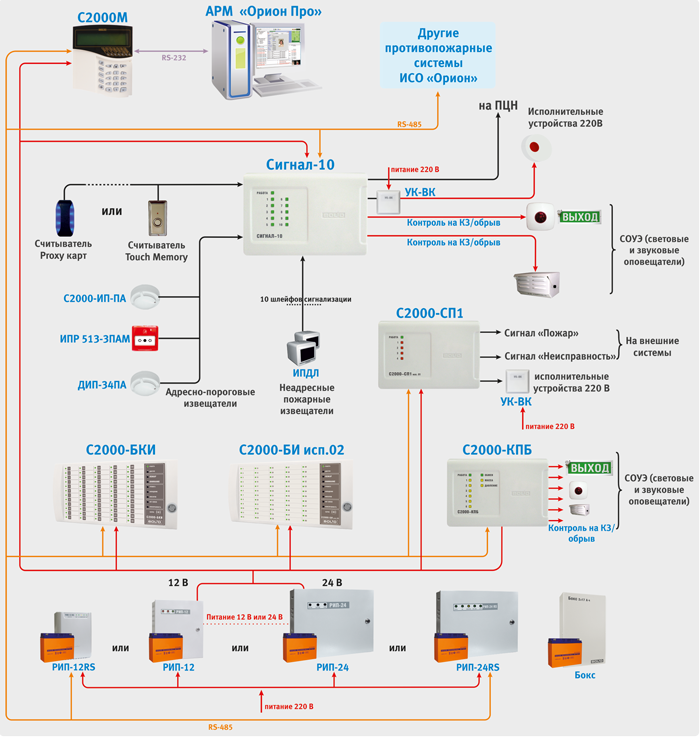
Addressable threshold fire alarm system in ISO "Orion" can be built on the basis of a block-modular control panel consisting of:
- Reception and control unit “Signal-10” with address-threshold mode of alarm loops;
- Smoke optical-electronic threshold-addressable detectors "DIP-34PA";
- Thermal maximum-differential threshold-addressable detectors “S2000-IP-PA”;
- Manual threshold-addressable detectors "IPR 513-3PAM".
Additionally, relay blocks “S2000-SP1” and “S2000-KPB” can be used to expand the number of system outputs; display and control units “S2000-BI isp.02” and “S2000-BKI” for visual display of the status of instrument inputs and convenient control of them from the duty station.
When connecting the indicated detectors to the “Signal-10” block, the device loops must be assigned type 14 - “Fire addressable-threshold”. Up to 10 addressable detectors can be connected to one addressable threshold loop, each of which is capable of reporting its current status upon request of the device. The device periodically polls addressable detectors, monitoring their performance and identifying a faulty or triggered detector.
Each addressable detector is considered as an additional virtual input of the BOD. Each virtual input can be disarmed and armed using a command from the network controller (S2000M remote control). When arming or disarming a threshold-addressable loop, those addressable detectors (virtual inputs) that belong to the loop are automatically removed or taken.
The addressable threshold loop can be in the following states (states are given in order of priority):
- “Fire 2” – at least one addressable detector is in the “Manual fire” state or two or more addressable detectors connected to the same input or belonging to the same zone have switched to the “Fire 1” state in no more than 120 s;
- “Fire 1” - at least one addressable detector is in the “Fire 1” state;
- “Disabled” – at least one addressable detector is in the “Disabled” state (within 10 seconds the device has not received a response from the detector. That is, there is no need to use a loop break when removing the detector from the socket, and the functionality of all other detectors is maintained);
- “Fault” – at least one addressable detector is in the “Fault” state;
- “Failure to arm” – at the time of arming, at least one addressable detector was in a state other than “Normal”;
- “Dusty, maintenance required” – at least one addressable detector is in the “Dusty” state;
- “Disarmed” (“Disarmed”) – at least one addressable detector has been disarmed;
- “On guard” (“Armed”) – all addressable detectors are normal and armed.
When organizing an address-threshold security alarm system to operate outputs, you can use operating tactics similar to those used in a non-addressable system.
In Fig. An example of organizing an address-threshold fire alarm system using the Signal-10 block is given.
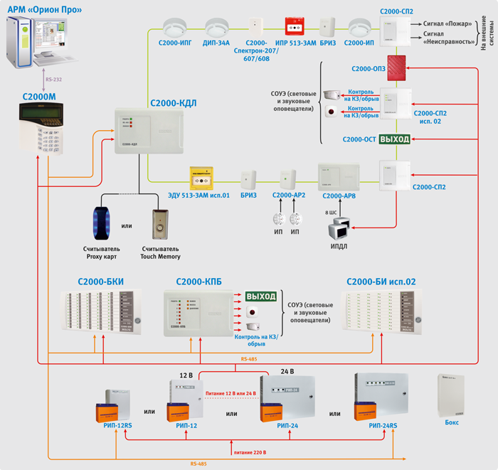
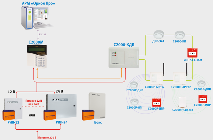
Addressable analogue fire alarm system in ISO "Orion" is built on the basis of a block-modular control panel, consisting of:
- Control and control panel “S2000M”;
- Two-wire communication line (BPK) controllers “S2000-KDL” or “S2000-KDL-2I”;
- Fire smoke optical-electronic addressable analogue detectors "DIP-34A";
- Fire addressable analog gas and thermal maximum-differential fire detectors "S2000-IPG", designed to detect fires accompanied by the appearance carbon monoxide indoors, by monitoring changes chemical composition air and ambient temperature;
- Fire addressable thermal explosion-proof detectors “S2000-Spectron-101-Exd-M”, “S2000-Spectron-101-Exd-N”;
- Fire addressable infrared (IR) flame detectors “S2000-Spektron-207”;
- Multi-band addressable fire detectors (IR/UV) “S2000-Spectron-607-Exd-M” and “S2000-Spectron-607-Exd-H”
- Multi-band addressable fire detectors (IR/UV) “S2000-Spektron-607”;
- Multi-band (IR/UV) addressable fire detectors “S2000-Spektron-608”;
- Multi-band (IR/UV) explosion-proof addressable fire detectors “S2000-Spektron-607-Exi”;
- Fire addressable flame detectors, multi-band (IR/UV) explosion-proof “S2000-Spectron-608-Exi”;
- Fire manual addressable call points “IPR 513-3AM”;
- Elements remote control addressable “EDU-513-3AM”, “EDU-513-3AM isp.01”, intended for generating control signals for automation systems and unlocking ACS doors and emergency exits;
- Branching and insulating blocks “BREEZ”, “BREEZ isp.01”, designed for isolating short-circuited sections with subsequent automatic recovery after the short circuit is removed. “BREEZE” is installed in the line as a separate device, “BREEZE isp.01” is built into the base of fire detectors “S2000-IP” and “DIP-34A”. Special versions of detectors “DIP-34A-04”, “S2000-IP-04” and “IPR 513-3AM isp.01” with built-in short circuit insulators are also produced.
- Address expanders “S2000-AR1”, “S2000-AR2”, “S2000-AR8”. Devices designed for connecting non-addressable four-wire detectors. Thus, conventional threshold detectors, for example, linear detectors, can be connected to the addressable system.
- Alarm loop extension units “S2000-BRShS-Ex”, designed for connecting non-addressable intrinsically safe detectors (see section “Explosion-proof solutions...”).
- Addressable radio expanders "S2000R-APP32", designed for connecting radio channel devices of the "S2000R" series into a two-wire communication line.
- Devices of the S2000R series:
- Fire point smoke optical-electronic addressable analogue radio channel detectors “S2000R-DIP”;
- Fire thermal maximum-differential addressable analogue radio channel detectors “S2000R-IP”;
- Fire manual addressable call points "S2000R-IPR".
When organizing an addressable analogue fire alarm system, the devices “S2000-SP2” and “S2000-SP2 isp.02” can be used as relay modules. These are addressable relay modules, which are also connected to the S2000-KDL via a two-wire communication line. “S2000-SP2” has two relays of the “dry contact” type, and “S2000-SP2 isp.02” has two relays with monitoring of the health of the actuator connection circuits (separately for OPEN and SHORT CIRCUIT). For the S2000-SP2 relay, you can use operating tactics similar to those used in a non-addressable system.
The system also includes addressable security and fire sound sirens “S2000-OPZ” and light table address sirens “S2000-OST”. They are connected directly to the DPLS without additional relay units, but require a separate 12 - 24 V power supply.
The S2000R-APP32 radio expander allows you to control the S2000R-Siren light-sound radio channel siren.
Additionally, relay blocks “S2000-SP1” and “S2000-KPB” can be used to expand the number of system outputs; indication and control units “S2000-BI” and “S2000-BKI” for visual display of the status of instrument inputs and convenient control of them from the duty officer’s post.
The two-wire communication line controller actually has two alarm loops, to which a total of up to 127 addressable devices can be connected. These two loops can be combined to organize a ring structure of the DPLS. Addressable devices are fire detectors, addressable expanders or relay modules. Each addressable device occupies one address in the controller memory. Address extenders occupy as many addresses in the controller’s memory as loops can be connected to them (“S2000-AP1” - 1 address, “S2000-AP2” - 2 addresses, “S2000-AP8” - 8 addresses). Addressable relay modules also occupy 2 addresses in the controller memory. Thus, the number of protected premises is determined by the addressable capacity of the controller. For example, with one “S2000-KDL” you can use 127 smoke detectors or 87 smoke detectors and 20 addressable relay modules. When addressable detectors are triggered or when addressable expander loops are disrupted, the controller issues an alarm notification via the RS-485 interface to the S2000M control panel.
The S2000-KDL-2I controller is functionally the same as the S2000-KDL, but has an important advantage - a galvanic barrier between the DPLS terminals and the power supply terminals, the RS-485 interface and the reader. This galvanic isolation will improve the reliability and stability of the system at facilities with complex electromagnetic environments. It also helps to exclude the flow of equalizing currents (for example, in case of installation errors), the influence of electromagnetic interference or interference from equipment used at the site or in the event of external influences of a natural nature (lightning discharges, etc.).
For each addressable device in the controller, the input type must be specified. The input type indicates to the controller the tactics of the zone and the class of detectors included in the zone.
Type 2 - "Combined firefighter"
This type of input is intended for addressable expanders “S2000-AR2”, “S2000-AR8” and “S2000-BRShS-Ex” (see section “Explosion-proof solutions...”), in which the controller will recognize CC states such as “Normal” , “Fire”, “Open” and “Short circuit”. For “S2000-BRShS-Ex”, the “Attention” state can additionally be recognized.
Possible input states:
- “Attention” – “S2000-BRShS-Ex” recorded the AL state corresponding to the “Attention” state;
- “Fire” – the address expander has recorded the AL state corresponding to the “Fire” state;
- “Break” – the address expander has recorded the loop state corresponding to the “Break” state;
- “Short circuit” – the address expander has recorded the AL state corresponding to the “Short circuit” state;
Type 3 – "Fire Thermal"
This type of input can be assigned to “S2000-IP” (and its modifications), “S2000R-IP” operating in differential mode, to “S2000-AR1” various designs, controlling non-addressable fire detectors with a “dry contact” type output, as well as addressable “S2000-Spectron” detectors of all modifications. Possible input states:
- “Taken” – the input is normal and fully controlled;
- “Disabled (removed)” – the input is normal, only faults are monitored;
- “Failure to arm” – the controlled parameter of the control system was not normal at the time of arming;
- “Arming delay” – the input is in the arming delay state;
- “Fire” – the addressable heat detector has recorded a change in temperature corresponding to the condition for switching to the “Fire” mode (differential mode); the address expander recorded the CC state corresponding to the “Fire” state;
- “Fire2” – two or more inputs belonging to the same zone went into the “Fire” state in no more than 120 s. It will also assign the "Fire2" state to all inputs associated with this zone that had the "Fire" state;
- “Fire equipment malfunction” – the measuring channel of the addressable heat detector is faulty.
Type 8 – “Smoke addressable analog”
This type of input can be assigned to “DIP-34A” (and its modifications), “S2000R-DIP”. In standby mode, the controller requests numerical values corresponding to the level of smoke concentration measured by the detector. For each input, pre-warning “Attention” and “Fire” warning thresholds are set. Trigger thresholds are set separately for the “NIGHT” and “DAY” time zones. Periodically, the controller requests the dust content value of the smoke chamber, the resulting value is compared with the “Dusty” threshold, which is set separately for each input. Possible input states:
- “Taken” – the entrance is normal and fully controlled, the thresholds “Fire”, “Attention” and “Dusty” are not exceeded;
- “Disabled (removed)” – only the “Dusty” threshold and faults are monitored;
- “Arming delay” – the input is in the arming delay state;
- “Failure to arm” – at the time of arming, one of the “Fire”, “Attention” or “Dusty” thresholds has been exceeded or a malfunction is present;
- “Fire2” – two or more inputs belonging to the same zone went into the “Fire” state in no more than 120 s. It will also assign the "Fire2" state to all inputs associated with this zone that had the "Fire" state;
- “Fire equipment malfunction” – the measuring channel of the addressable detector is faulty;
- “Service required” – the internal threshold for automatic compensation of dust content in the smoke chamber of the addressable detector or the “Dusty” threshold has been exceeded.
Type 9 - "Thermal Addressable Analogue"
This type of input can be assigned to “S2000-IP” (and its modifications), “S2000R-IP”. In standby mode, the controller requests numerical values corresponding to the temperature measured by the detector. For each input, the temperature thresholds for the preliminary warning “Attention” and the warning “Fire” are set. Possible input states:
- “Arming delay” – the input is in the arming delay state;
- “Attention” – the “Attention” threshold has been exceeded;
- “Fire” – the “Fire” threshold has been exceeded;
- “Fire2” – two or more inputs belonging to the same zone went into the “Fire” state in no more than 120 s. It will also assign the "Fire2" state to all inputs associated with this zone that had the "Fire" state;
Type 16 – "Firefighter manual"
This type of input can be assigned to “IPR 513-3A” (and its versions); "S2000R-IPR"; AL of address expanders. Possible input states:
- “Taken” – the input is normal and fully controlled;
- “Disabled (removed)” – the input is normal, only faults are monitored;
- “Failure to arm” – the controlled parameter of the control system was not normal at the time of arming;
- “Arming delay” – the input is in the arming delay state;
- “Fire2” – targeted manual call point transferred to the “Fire” state (pressing a button); the address expander recorded the CC state corresponding to the “Fire” state;
- “Short circuit” – the address expander has recorded the CC state corresponding to the “Short circuit” state;
- “Fire equipment malfunction” – malfunction of the addressable manual call point.
Type 18 - "Fire Launcher"
This type of input can be assigned to addressable “EDU 513-3AM”, UDP and their versions; AL of address expanders with connected EDU and UDP. Possible input states:
- “Disabled (removed)” – the input is normal, only faults are monitored;
- “Arming delay” – the input is in the arming delay state;
- “Activation of the remote start device” – the EDU is transferred to the active state (glass broken, button pressed, etc.); the address expander recorded the CC state corresponding to the “Fire” state
- “Restoring the remote start device” – the EDU is returned to its original state; the address expander recorded the CC state corresponding to the “Normal” state;
- “Break” – the address expander has recorded the CC state corresponding to the “Break” state;
- “Short circuit” – the address expander has recorded the CC state corresponding to the “Open” state;
- “Fire equipment malfunction” – EDU malfunction.
Type 19 – "Firefighter gas"
This type of input can be assigned to S2000-IPG. In standby mode, the controller requests numerical values corresponding to the carbon monoxide content in the atmosphere measured by the detector. For each input, pre-warning “Attention” and “Fire” warning thresholds are set. Possible input states:
- “Taken” – the input is normal and fully controlled, the “Fire” and “Attention” thresholds are not exceeded;
- “Disabled (removed)” – only faults are monitored;
- “Arming delay” – the input is in the arming delay state;
- “Failure to arm” – at the time of arming, one of the thresholds “Fire”, “Attention” has been exceeded or a malfunction is present;
- “Attention” – the “Attention” threshold has been exceeded;
- “Fire” – the “Fire” threshold has been exceeded;
- “Fire2” – two or more inputs belonging to the same zone went into the “Fire” state in no more than 120 s. It will also assign the "Fire2" state to all inputs associated with this zone that had the "Fire" state;
- “Fire equipment malfunction” – the measuring channel of the addressable detector is faulty.
Additional parameters can also be configured for fire inputs:
- Automatic re-arming - instructs the device to automatically arm an unarmed alarm as soon as its resistance is normal within 1 s.
- Without the right to disarm – serves to enable permanent control of the zone, that is, a zone with this parameter cannot be disarmed under any circumstances.
- The arming delay determines the time (in seconds) after which the device attempts to arm the alarm after receiving the corresponding command. Non-zero “Arming Delay” in fire alarm systems is usually used if, before arming a non-addressed alarm loop, it is necessary to turn on the device output, for example, to reset the power supply to 4-wire detectors (relay control program “Turn on for a while before arming”).
The S2000-KDL controller also has a circuit for connecting readers. You can connect various readers operating via the Touch Memory or Wiegand interface. From the readers it is possible to control the state of the controller inputs. In addition, the device has functional indicators of the operating mode status, DPLS lines and an exchange indicator via the RS-485 interface. In Fig. An example of organizing an addressable analogue fire alarm system is given.
As mentioned above, the radio channel expansion of the addressable analogue fire alarm system, built on the basis of the S2000-KDL controller, is used for those premises of the facility where laying wire lines for one reason or another is impossible.
The S2000R-APP32 radio expander provides constant monitoring of the presence of communication with 32 radio devices of the S2000R series connected to it and monitoring the status of their power supplies. Radio channel devices automatically monitor the performance of the radio channel, and if it is highly noisy, they automatically switch to a backup communication channel.
Operating frequency ranges of the radio channel system: 868.0-868.2 MHz, 868.7-869.2 MHz. The emitted power in transmission mode does not exceed 10 mW.
The maximum range of radio communication in open areas is about 300 m (the range of operation when installing a radio system indoors depends on the number and material of walls and ceilings in the path of the radio signal).
The system uses 4 radio frequency channels. At the same time, up to 3 “S2000R-APP32” can operate on each channel in the radio visibility zone.
“S2000R-APP32” connects directly to the DPLS of the “S2000-KDL” controller and occupies one address in it. In this case, each radio device will also occupy one or two addresses in the S2000-KDL address space, depending on the selected operating mode.
The operating algorithms of radio devices are described above in the section devoted to the types of “S2000-KDL” inputs.
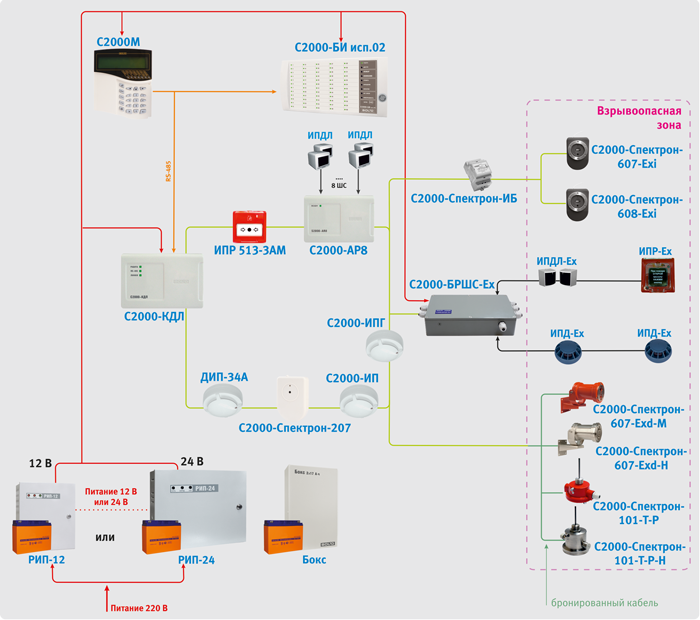
If it is necessary to equip a fire alarm for an object with explosive zones, together with an addressable analogue system built on the basis of the S2000-KDL controller, it is possible to use a line of specialized addressable explosion-proof detectors.
Multi-band flame detectors (IR/UV) “S2000-Spectron-607-Exd-M” and “S2000-Spectron-607-Exd-H” (with special protection against false alarms for electric arc welding); thermal "S2000-Spectron-101-Exd-M", "S2000-Spectron-101-Exd-N" are manufactured in accordance with the requirements for explosion-proof equipment group I and subgroups IIA, IIB, IIC according to TR TS 012/2011, GOST 30852.0 (IEC 60079-0), GOST 30852.1 (IEC 60079-1) and corresponds to the explosion protection marking РВ ExdI/1ExdIICT5. The explosion protection of these detectors is ensured by the shell. Thus, the DPLS line in a hazardous area must be made with an armored cable. Connection of DPLS to detectors is carried out through special cable entries. Their type is determined when ordering depending on the method of cable protection.
The shell of detectors marked – Exd-H is made of of stainless steel. They are recommended to be installed at facilities with chemically aggressive environments (for example, petrochemical industry facilities).
For operation of detectors in the area low temperatures(below - 40oC) there is a built-in thermostat - a device that, using heating elements, in automatic mode is capable of maintaining operating temperature inside the case. To operate the thermostat, an additional power source is required. Heating is turned on at a temperature of -20oC. Multi-range flame detectors (IR/UV) "S2000-Spectron-607-Exi" (with special protection against false alarms for electric arc welding) and multi-range flame detectors (IR/UV) "S2000-Spectron-608-Exi" have an explosion protection level of "extra explosion-proof" » marked OExiaIICT4 X according to TR CU 012/2011, GOST 30852.0 (IEC 60079-0), GOST 30852.10 (IEC 60079-11). The explosion protection of these detectors is ensured by an intrinsically safe “ia” circuit and an antistatic shell. Connection to the DPLS is carried out using a conventional cable through the spark-proof barrier “S2000-Spectron-IB”, installed outside the hazardous area.
Addressable explosion-proof detectors operate according to the “Fire Thermal” tactic. The algorithm of their operation is described above in the section devoted to the types of “S2000-KDL” inputs.
To connect other types of explosion-proof detectors, intrinsically safe barriers “S2000-BRShS-Ex” are used. This block provides protection at the level of an intrinsically safe electrical circuit. This method of protection is based on the principle of limiting the maximum energy accumulated or released by an electrical circuit in emergency mode, or dissipating power to a level significantly below the minimum energy or ignition temperature. That is, the voltage and current values that can enter the danger zone in the event of a malfunction are limited. The intrinsic safety of the unit is ensured by galvanic isolation and the appropriate selection of the values of electrical clearances and creepage paths between intrinsically safe and associated intrinsically hazardous circuits, limiting voltage and current to intrinsically safe values in the output circuits through the use of compound-filled spark protection barriers on zener diodes and current-limiting devices, ensuring electrical clearances, leakage paths and integrity of spark protection elements, including due to their sealing (filling) with a compound.
"S2000-BRSHS-Ex" provides:
- receiving notifications from connected detectors via two intrinsically safe loops by monitoring their resistance values;
- power supply to external devices from two built-in intrinsically safe power supplies;
- relaying alarm messages to the two-wire communication line controller.
The X sign after the explosion protection marking means that only explosion-proof electrical equipment with the type of explosion protection “intrinsically safe electrical circuit i”, which has a certificate of conformity and a permit for use, is allowed to be connected to the connecting devices “S2000-BRShS-Ex” marked “intrinsically safe circuits”. Federal service on environmental, technological and nuclear supervision in explosive areas. “S2000-BRSHS-Ex” occupies three addresses in the address space of the “S2000-KDL” controller.
It is possible to connect any threshold fire detectors to the S2000-BRSHS-Ex. Today, the company ZAO NVP "Bolid" supplies a number of sensors for installation inside an explosive zone (explosion-proof version):
- “IPD-Ex” - optical-electronic smoke detector;
- "IPDL-Ex" - optical-electronic linear smoke detector;
- "IPP-Ex" - infrared detector flame;
- "IPR-Ex" - manual call point.
The “S2000-BRShS-Ex” inputs operate according to the “Combined Firefighter” tactic. The algorithm of their operation is described above in the section devoted to the types of “S2000-KDL” inputs.
In some cases, when building a fire alarm, a personal computer with specialized software preinstalled on it is used. The software can expand the functionality of the S2000M remote control, namely, it can be used to organize a control post, maintain a log of events and alarms, indicate the causes of alarms, collect statistics on addressable fire detectors, and also to generate various reports. These are the so-called automated workstations (AWS). Thus, in the ISO “Orion” architecture, when constructing fire alarm systems, the automated workplace is an additional means of dispatching and is not actually part of the control panel or control device.
To organize automated workstations in the Orion ISO, the Orion Pro automated workplace software is used. The inclusion of automated workstations in the system transfers it to the upper level of the three-level model.
PCs with Orion PRO workstation allow you to implement the following functions:
- Accumulation of PS events in the database (according to PS alarms, operator reactions to these alarms, etc.);
- Creating a database for a protected object - adding loops, sections, relays to it, arranging them on floor plans;
- Creation of access rights for duplicating PPKUP functions for managing PS objects (alarm resets), assigning them to duty operators;
- Placement of logical substation objects (loops, partition areas, relays) on graphic floor plans of premises
- Polling of control and control devices connected to the PC. That is, from a computer you can simultaneously interrogate several subsystems, each of which is a control panel controlled by the “S20000M” remote control;
- Displaying the state of the protected object on graphic plans of premises, duplicating the functions of the control panel in terms of managing the logical objects of the PS (inputs, sections);
- Registration and processing of fire alarms occurring in the system, indicating the reasons, service marks, as well as their archiving;
- Providing information about the state of PS objects in the form of an object card;
- Generating and issuing reports on various PS events;
- Camera display CCTV, as well as managing the state of these cameras.
The assignment of automatic fire alarm tasks to software modules is shown in Fig.

The assignment of automatic fire alarm tasks to software modules is shown in Fig. 8. It is worth noting that the devices are physically connected to the system computer on which the “Orion Pro Operational Task” software module is installed. The device connection diagram is shown in structural diagram ISO "Orion". The block diagram also shows the number of jobs that can be simultaneously used in the system (AWS software modules). Software modules can be installed on computers in any way - each module on a separate computer, a combination of any modules on a computer, or installing all modules on one computer.
All devices intended for fire alarms in ISO "Orion" are powered from low-voltage power supplies (VPS) direct current. Most devices are adapted to a wide range of power supply voltages - from 10.2 to 28.4 V, which allows the use of sources with a rated output voltage of 12 V or 24 V. A personal computer with a dispatcher workstation can occupy a special place in the fire alarm system. It is usually powered from the mains alternating current and its power supply is provided by UPS type sources.
Distributed placement of equipment over a large facility, which is easily implemented in the Orion ISO, requires providing power to the devices at their installation sites. Given the wide range of supply voltages, it is possible, if necessary, to place power supplies with an output voltage of 24 V at a distance from consumer devices, even taking into account a significant voltage drop on the wires. However, the most convenient in this regard seems to be the provision of power in an addressable analogue fire alarm system based on the S2000-KDL controller. IN in this case addressable detectors and relay modules S2000-SP2 connected to the two-wire signal communication line of the S2000-KDL controller will receive power via this line. The exceptions will be the “S2000-SP2 isp.02” and “S2000-BRShS-Ex” units, which require separate power supplies.
If we consider the case of radio expansion of an addressable analog system, then in accordance with clause 4.2.1.9 all radio devices have a main and backup autonomous power supply. At the same time, the average operating time of radio devices from the main source is 5 years and from the backup source is 2 months. “S2000-APP32” can be powered either from an external source (9 -28 V) or from a DPLS. Due to the high current consumption of the device, in most cases it is recommended to use the first power supply scheme.
Basic normative document, which determines the parameters of the IE for fire alarms - . In particular:
1) The IE must have an indication:
Availability (within normal limits) of main and backup or standby power supplies (separately for each power supply input);
Availability of output voltage.
2) The IE must ensure the generation and transmission of information to external circuits about the absence of output voltage, input power supply voltage at any input, discharge of batteries (if any) and other faults controlled by the IE.
3) IE must have automatic protection from a short circuit and an increase in the output current above the maximum value specified in the TD on the IE. In this case, the IE should automatically restore its parameters after these situations.
Depending on the size of the facility, powering the fire alarm system may require from one power source to several dozen power sources. In large, distributed facilities, power supply design comes down to a choice between using low-power power supplies with short runs of power cables and using fewer high-power sources, with multiple power cables running to the devices. To simplify this task, there is a wide range of certified power supplies for fire alarms with different output voltages and load currents: RIP-12 isp.02P, RIP-12 isp.04P, RIP-12 isp.06, RIP-12 isp.15, RIP -12 isp.16, RIP-12 isp.17, RIP-24 isp.01P, RIP-24 isp.02P, RIP-24 isp.06, RIP-24 isp.15.
All RIPs for powering fire automatic equipment have three separate relay outputs, galvanically isolated from other circuits and from each other. The RIP monitors not only the presence or absence of the voltages listed above in paragraph 2) but also their deviations from the norm.
All devices and instruments included in the fire alarm system belong to the first category of electrical receivers. This means that when installing a fire alarm, it is necessary to implement a system uninterruptible power supply. If the facility has two independent high-voltage power supply inputs, or the ability to use a diesel generator, then it is possible to develop and apply an automatic transfer switch (ATS) circuit. In the absence of such a possibility, uninterruptible power supply is forced to be compensated by redundant power supply using sources with a built-in or external low-voltage battery. In accordance with SP 513130-2009, the battery capacity is selected based on the calculated current consumption of all (or group) fire alarm devices, taking into account ensuring their operation at backup power in standby mode for 24 hours plus 1 hour in alarm mode. To increase the operating time of the RIP in backup mode, additional batteries (2 pcs.) with a capacity of 17Ah installed in Box-24/17M5-R (Box-24 isp.01) can be connected to RIP-24 isp.01P. This device is a metal case with built-in protection elements against overcurrent and battery reverse polarity.
At some facilities where there are special requirements for the reliability of fire alarm operation, you can use RIP-12 RS, RIP-12 isp.51, RIP-12 isp.16, RIP-24 isp.50, RIP-24 isp.51, which During operation (continuously), they measure the network voltage, battery voltage, output voltage and output current and transmit the measured values (on request) to the S2000M remote control or Orion Pro workstation. In this case, without laying additional wires for monitoring, on the S2000M remote control or on a computer with an Orion Pro workstation, you can receive the following messages: “Network failure”, “Power supply overload”, “Charger malfunction”, Power supply malfunction”, “Fault batteries”, “Hacking the source housing”, “Disconnecting the output voltage”.
Also, facilities can use power sources that have additional positive qualities.
RIP-12 isp.04P:
- built-in thermal sensor for monitoring the temperature inside the case and controlling the battery charging process;
- checking the condition of the battery with a test load;
- charger health check
or RIP-12 isp.06, RIP-24 isp.06:
- individual voltage control on each of the two installed batteries;
- built-in two-pole mains voltage switch - circuit breaker;
- long time reservations.
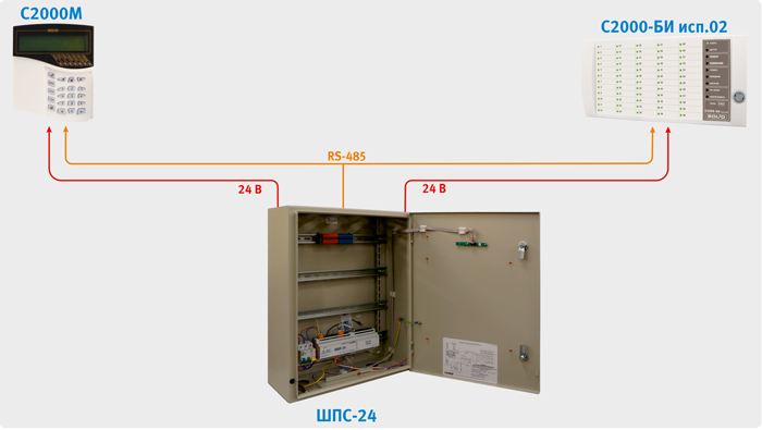
The use of fire alarm cabinets can simplify the task of placing fire alarm devices on site. Currently, two cabinets are produced: “ShPS”, which can accommodate up to 5 devices such as S2000-KDL, S2000-4, etc., with housings for mounting on a DIN rail, and “ShPS-24”, which can accommodate up to 6 devices various types and additional blocks(such as “UK-VK”, “BZL”, etc.).
The cabinets include:
- RIP-12 RS board with an output voltage of 12V and a current of 3A for “ShPS”;
- or MIP-24-2A RS board with an output voltage of 24V and a current of 2A for “ShPS-24”;
- switching unit that allows you to connect up to 6 independent consumers (devices) to the RIP output, including external devices– S2000M, S2000-BI, etc. This block also has 6 outputs for connecting devices to the RS-485 interface;
- mains voltage distribution buses for connecting, if necessary, devices powered by 220V.
The cabinets have the ability to install two 12 V batteries with a capacity of 17 Ah. An automatic switch is provided in the mains voltage circuit.
As in burglar alarms, fire alarm devices and devices can be exposed to short-term overvoltages, which can be protected against using the recommendations given in the “Security Alarm” section.
Since ancient times, people have tried to protect their homes from such elements as fire. Progress does not stand still, and today for the safety of premises they install fire alarms. The desire to install an alarm system comes not only from the owner, but is also established at the legislative level.
Fire alarm system
The fire alarm system is a set of sensors installed in one area and connected to a common fire station. The fire alarm recognizes a fire and notifies you of its location. Its main components are receiving devices, communication lines, and sensors. It is the last component that transmits the fire signal to the control panel. Most often they react to smoke, light, and heat. The receiving devices receive the signal from the sensors and recognize the location of the fire, which activates the alarm.
Fire alarm system is a complex electrical installation with a set of technical means that are responsible for detecting the source of fire in order to avoid damage to property and health.
It was developed for quick fire detection.
Automatic fire alarm
According to the principle of its operation, it is no different from a conventional fire alarm, but several more functions have been added to the already existing ones. For example, it automatically notifies people about a fire, and also connects fire extinguishing and smoke removal systems.
Automatic fire alarm generates commands to close supply ventilation Fresh air, blocking elevators, turning off power sources and switching to emergency lighting.
This system is characterized by the presence of several types of fire extinguishing: water, powder, gas. The type of fire extinguishing is determined depending on the room in which the alarm will be installed.
For all fire safety systems, the main criterion for determining quality is the degree of its reliability. An important component is the ability to detect fire at initial stage and minimizing false alerts.