Three-channel remote control system. Device remote control diagram
Wireless calls industrial production may have a different appearance (photo 1), but in their composition mandatory elements are a remote control transmitter and a radio signal receiver. As a rule, such wireless calls operate at a frequency of 433 MHz and, due to the very low transmitter power, do not interfere with or affect the operation of other household appliances.
However, the range of such calls stated in the passport data is almost always greatly overestimated, sometimes by 2.5-3 times. So, if the declared range (indicated in the passport) is, for example, 80 m, then the real distance of the reliable operation of the call will most likely be no more than 30 m. With an increase in the passport range, their price always increases proportionally. For example, a wireless call with a working radius of 100 m (in reality - about 35 m) already costs more than 1,100 rubles.
In fact, it doesn’t matter which call you use, since its real “range” can almost always be increased at least 1.5...2 times by connecting an external antenna. Therefore, we will consider the most “budget” and simple options. The receiver antenna should not be touched, since at a radio signal frequency of 433 MHz, increasing its length does not lead to a significant increase in the distance of reliable operation of the transmitter-receiver combination.
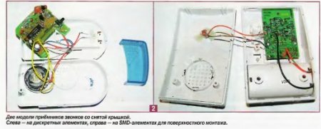 Photo 2 shows two different appearance models, but call receivers identical in circuit design with with the lid removed. They have the same scheme, but the execution is different. In particular, the one on the left in photo 2 is assembled using discrete elements, and the one on the right is assembled using elements in SMD surface-mount packages.
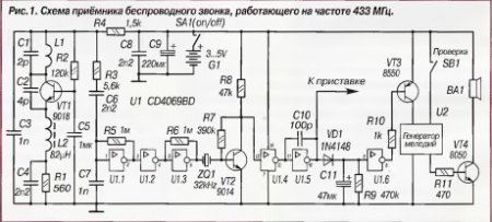 In Fig. Figure 1 shows a diagram of the receiver of one of the simplest and cheapest wireless calls. Pin 10 of the U1 chip has an active high level when a radio signal arrives from the remote control transmitter (when its button is pressed). Pins 11 and 12 of U1, on the contrary, have a high level at rest and a low logical level when a control signal is received from the remote control transmitter. Both of these signals can be used to control various devices, if you connect a simple set-top box to the receiver.
DEVELOPMENT OF THE WIRELESS CALL RECEIVER
In order for the pump remote control device to work effectively, for example, when you press the button on the remote control transmitter for the first time, it connects the pump to a 220 V network, and when you press it again, it turns it off, you will need to assemble a simple device and connect it to a ready-made wireless call receiver board. In Fig. Figure 2 shows a diagram of such a device that allows you to turn the pump on and off without laying additional wires.
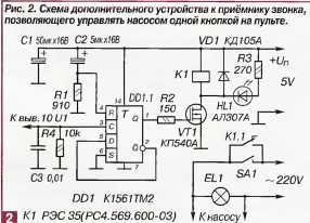 The submersible pump is connected in parallel with an EL1 incandescent lamp, which is an indicator light. (Thanks to this, you can verify from a distance that the command from the transmitter has been received, the remote device has worked, and the pump has turned on.) Board additional device(Fig. 2) are connected to the radio call receiver board (Fig. 1) with unshielded wires of type MGTF-0.4 (or similar). In this case, the common wire of the set-top box is connected to the negative power supply of the receiver, and the input of the DD1.1 chip (K1561TM2) is connected to pin 10 of the CD4069BD chip (in some models - D4069UBC). To prevent a melodic bell from sounding during the transmission of a control signal, it is enough to unsolder one of the conductors leading to the dynamic capsule.
The additional device circuit is working in the following way. When the power is turned on at the first moment of time, the R input of the DD1.1 trigger, thanks to the discharged capacitor C2, receives a high logical level, which resets the trigger and its direct output Q (pin 1 of the DD1.1 microcircuit) is set to a low logical level. Therefore, transistor VT1 is closed, relay K1 is de-energized, lamp EL1 is not lit, and the pump does not work.
About a third of a second after switching on, capacitor C2 will charge almost to the supply voltage and the level at the input R of the trigger (pin 4 of DD1.1) will change to low. Now it is ready to receive signals from the clock input C, which, as follows from the diagram, has a low initial level.
When a radio signal is transmitted from the remote control transmitter, it is received by the call receiver and a high logical level appears at pin 10 of the U1 chip, which is supplied to the input C of the DD1.1 chip of the additional device. As a result, the trigger is transferred to another stable state - now a high voltage level appears at its direct output Q (pin 1 of DD1.1). Transistor VT1 turns on relay K1, and its contacts, in turn, close the electrical power circuit of the lighting lamp EL1 and the submersible pump. The trigger can remain in this state for as long as desired, until the next positive edge of the pulse arrives at input C (the next key press on the remote control), which will switch the trigger to its original state. In this case, the lighting lamp EL1 will go out and the pump will turn off.
The maximum load (pump) power that can be connected to this remote control depends on the parameters electromagnetic relay K1 and for relays of type RES35 should not exceed 350 W.
All parts of the set-top box are easily placed on a board measuring 30x40 mm, which, together with the connecting wires, is placed in the standard housing of the call receiver in the battery compartment. To reduce electrical interference, it is desirable that the wires connecting the device to the power source and going from relay K1 to the pump have a cross-section of at least 1.5 mm2 and be as short as possible.
Fixed resistors - type MLT-0.25 (MF-25). Oxide capacitors are type K50-26 for an operating voltage of at least 16 V. The remaining non-polar capacitors are type KM-6B. The DD1 chip is of the K1561TM2 type; it can be replaced by the K561TM2 without compromising operating efficiency. You can also use the K561TM1 trigger, but in this case you will have to make appropriate changes to the circuit. Transistor VT1 is a field-effect type KP540A with high input resistance. This allows you to minimize the load on the output of the trigger of the DD1 microcircuit. Instead of the KP540A, you can use a field-effect transistor from any of the KP540 series or its foreign analogues BUZ11, IRF510, IRF521.
Relay K1 can be replaced with RES43 (version RS4.569.201) or another one designed for operating voltage
4...4.5 V and current 10...50 mA. It is not advisable to install a relay with an operating current of more than 100 mA into the device. LED HL1 - any, with its help it is convenient to control the operation of the relay. If necessary, elements HL1 and R3 can be excluded from the circuit. The additional switch SA1 allows you to control the pump manually.
In the basic version, the bell receiver is powered by two 1.5 V finger elements. But when using a bell as part of a remote pump control, it is better to use a network stabilized power supply with a voltage of 5 V to power it. The current consumption from the power supply of the receiving unit does not exceed 10 mA in standby mode and increases to 50 mA when the relay is activated. For other types of relays, current consumption may have a different value. It is not worth increasing the supply voltage of the receiving unit to 12 V or more, since the range of reliable communication with the remote control transmitter will not increase. The optimal supply voltage for the receiver is 5...E V.
 DEVELOPMENT OF THE WIRELESS CALL REMOTE TRANSMITTER
The remote control transmitter for the wireless call is housed in a housing the size of a standard Matchbox. Its electrical diagram is shown in Fig. 3
3. The remote control transmitter circuit does not need modification. In order not to change the battery once a year, a TV-182-C type adapter with a stabilized output voltage of 12 V and a current of 0.5 A is used to power the transmitter.
To increase the operating range, a telescopic whip antenna from any portable radio is connected to the antenna contact on the printed circuit board using a piece of wire MGTF-0.8 (or similar). In extreme cases, it can be used as external antenna A similar one can be a stranded wire 35...40 cm long, fluffing (like flower petals) at the end its thin conductors (the diameter of the diverging petals is 6...8 cm). But such an improvised antenna works noticeably worse than a telescopic one. The greatest operating range with a telescopic antenna will be when it is extended approximately 35...40 cm.
Our everyday life increasingly includes various intelligent control systems. Washing machines They have been washing and drying themselves for a long time, cars park themselves, the lights in the house turn on themselves...
To control light, residents of the countries of the former USSR mainly use Sapphires or similar devices made in China. Costing around $15 - $20, these devices are capable of controlling an incandescent lamp, smoothly changing its brightness, and “simulating” the presence of the owners of the house. However, a number of significant shortcomings, primarily related to the inconvenience of remote control, discourage a number of potential buyers. Maybe I’m wrong, I apologize in advance to those whom I will offend with my subsequent statement, but I don’t know a single person who, having purchased Sapphire, would want to install another exactly the same DEVICE in their house...
The song of primitive single-channel dimmers is over... Multi-channel programmable devices are entering the scene...
I give a description of the 15-channel programmable dimmer “Sokol SHC-15”, developed at the request of the working people who wrote to me...
Brief specifications Sokol SHC-15 module:
15 control channels with dimming function (adjusting the brightness of incandescent lamps);
- 50 steps of smooth adjustment of the brightness of incandescent lamps ranging from 8% (the spiral barely glows) to 98%;
- control of channels from standard wall-mounted apartment switches without fixing the position;
- control all functions of the device and configure parameters using the Sokol SHC-15 Terminal program;
- the ability to connect lighting switches via one two-wire line, including via existing apartment wiring;
- control of channels using the remote control of the RC-5 system;
- training mode for remote control commands;
- smooth increase in lamp brightness when turned on (the function can be disabled through the setup program) for each control channel;
- smooth decrease in lamp brightness when turned off (the function can be disabled through the setup program) for each control channel;
- individual adjustment of minimum and maximum brightness for each control channel;
- the ability to enable/disable the brightness adjustment function for each control channel;
- trigger (the lamp turns on and off each time the channel control buttons are pressed again) or pulse operating mode (the lamp turns on at set time and goes out automatically) channels;
- setting the channel activity time in pulse mode in the range from 0.1 to 9999.9 seconds in increments of 0.1 seconds;
- the ability to use standard lighting switches mounted in a house (apartment) to control lighting;
- the presence of customizable commands “turn everything on” and “turn everything off” on the remote control and keyboard;
- the ability to select (set) channels that respond to commands “turn everything on and turn everything off”;
- customizable automatic shutdown timer in the absence of control commands;
- automatic channel shutdown time from 1 sec. until 23h.59m.59sec. in 1 second increments;
- complete galvanic isolation of channels both from each other and from the low-voltage part of the circuit;
- low price devices at self-assembly main module;
- restoration of the state of the channels in the event of a loss and restoration of the power supply (power supply to the module);
- remembering and restoring the last set brightness when the channel is turned on;
- customizable multi-tone sound signals of the module;
- protection against firmware freeze;
- adjustable “sensitivity” of the “contact anti-bounce” function of the manual control keyboard;
- practically unlimited channel load current, determined only by the power of the triac used.
So, to repeat this device, first of all we need to familiarize ourselves with the fundamental electrical diagram module, as well as its connection diagram...


Taking a quick glance at the mysterious intricacies of lines and nodes, a radio amateur, even with little experience, will understand that the main part of the device is the ATMega8A microcontroller from Atmel.
Those who are more experienced, looking at both options for connecting control buttons (switches), will immediately understand that decoding the number of the pressed key and command is carried out according to the voltage level supplied to the input of the microcontroller ADC. To reduce interference on the connecting wires of the control buttons, the voltage is measured close to the moment the mains voltage passes through zero.

To pulse-phase adjust the brightness of an incandescent lamp, it is necessary to accurately determine the same moment when the mains voltage crosses zero. For this, a node on transistor VT2 is used, from the collector of which voltage is supplied to the external interrupt input of the microcontroller. To reliably unlock optothyristors, the microcontroller generates bursts of pulses at the ports. The duration of each pulse is 15 μs, although the thyristors are normally unlocked already at a pulse duration of 8-12 μs.
The parallel-connected microcircuits DA1...DA3 in the connection diagram are photoreceivers of remote control commands TFMS5360 or similar, installed one in each room from which it is necessary to control the device... Photodetectors should be installed in the case together with filter capacitors. Since there are a great many models and manufacturers of photo sensor microcircuits, differing from each other not only in parameters, but also in location, the module connection diagram shows the pinout of the most common ones as a bonus. However, before purchasing a particular FP, make sure that it is designed for a frequency of 36 kHz. And the data will be delivered to your hands...
Looking at everything there, it is easy to notice that when connecting the device, all three phases of the power supply were used. Of course this is not necessary. By simply depicting them, I wanted to emphasize the possibility of installing and using the device to control lighting and electrical appliances in three-phase network. Regarding the fact that only three lamps and one socket are connected to the module, I’ll say: well, it’s a waste of time for me to redraw the same thing several times... there are 15 outputs - so use them at your discretion... and how to configure the module for this written at the bottom of the article...
I deliberately do not indicate the type of triacs. Look at the reference books... I can only say that almost any of the BT136, BT142 series will work. You just need to make sure from the reference book that the rated operating current is 2-3 times higher than the maximum load current, and the operating voltage is 600 V and higher... And do not forget about the cooling radiator if the load power exceeds 100 W. To protect the thyristor from surges high voltage, in the case of switching an inductive load (for example, a transformer or electric motor), it is advisable to use an RC circuit (C2 in the connection diagram).
The RS-232 port driver (COM port driver), DD2 chip, does not need to be installed on the board, especially if there is no need to control the device from a computer or you plan to use a ready-made USB-USART adapter (for example, a DATA cable from mobile phone). In the latter case, the board has jumpers that “short-circuit” DD2 and directly connect the rx and tx pins of the microprocessor to the output connector of the XS20 serial port.
To reduce height printed circuit board all tall elements, from the quartz resonator to the electrolytic capacitors, are “laid” horizontally. The size of the printed circuit board in this case was 85 x 82 mm, with a height of no more than 20 mm.
I almost forgot the most important thing: Due to the lack of microcontroller port pins in the circuit of 15 channel system The remote control can only be used with AT Mega 8A in a TQFP-32 surface mount package (for example ATmega8A-AU). In fact, the printed circuit board is designed for it. One of the advantages of using AT Mega 8A in the TQFP-32 package is that the board is almost half the size, and the cost of the microcontroller itself is one and a half times lower. However, it is possible to use the microcontroller in a DIP package (PDIP-28). In this case, the number of physical channels will be limited to 14. In addition, you will have to independently develop the device’s printed circuit board and use special firmware with a 14-channel software version. If you use a microcontroller in a DIP package (for example ATmega8A-PU), you should also take into account a slightly different connection diagram for the microcontroller pins. In addition to the different pin numbering, which can be viewed in the datasheet for the ATmega8A microcontroller, it should be noted that the keyboard and resistor R22 are connected to pin PC5 (ADC5) of the microcontroller in the DIP package, and not to pin ADC6, as in the TQFP package in the diagram. In this case, physical channel No. 15 “falls off” from the controller, since the output is already occupied. However, logically it remains accessible and visible in the control program. Don't ask why I did this. And so I will answer: it was a waste to remake the program for the PC. Here the question reasonably arises: “What will happen if the 15-channel version of the firmware is “poured” into a chip in a DIP package?” Answer: "There will be a 15-channel version without manual control (there is nowhere to connect keyboards!)."
Now according to the diagram: At first glance, with the mains transformer and other elements of the power circuit, everything is quite standard and simple. However, there are pitfalls here:
1. Capacitors C1 and C4 must have a capacity of at least 2200 microfarads. and 1000 uF, respectively, since optocouplers HL1...HL15 consume quite an impressive pulse current (up to 100 mA in total);
2. It is mandatory to install blocking ceramic capacitors where they are shown in the diagram;
3. It is mandatory to install inductor L1 in the power supply circuit of the microcontroller ADC;
4. Voltage stabilizer only 1.5 Amp 78L05;
5. Power transformer with a power of at least 2 W. and an output voltage as close as possible to 9 Volts (with a transformer for a different voltage of the secondary winding, you will need to select resistors R1, R2 to ensure the required minimum brightness of the lamp)...
When connecting a module for centralized control of house lighting, roller blinds, garage doors, sockets, etc., a number of measures should be taken to increase noise immunity:
1. Be sure to use a U-shaped surge protector in the power supply circuit of the module according to alternating current(in front of the power transformer, see connection diagram);
2. It is highly desirable to have an L-shaped filter (see connection diagram - F1) in front of the power part of the load control circuit (thyristors);
3. It is advisable to ground the common wire of the control module with a separate conductor with a cross-section of at least 1.5 mm. sq.;
4. To connect switches and photodetectors, it is recommended to use twisted pair Category 5 (preferably shielded) or shielded cable;
5. Install a ceramic and electrolytic capacitor in parallel to each photodetector (see connection diagram);
6. Do not lay unshielded low-current circuits in close proximity to power ones.
A list of elements for manufacturing the base unit of the device in pdf format, a table for calculating keyboard divider resistors and a drawing of a printed circuit board in *.lay (SL5.0) format can be downloaded from the link at the bottom of the article.
The program is designed to control loads using a personal computer and change module settings.

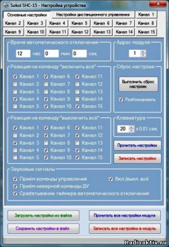
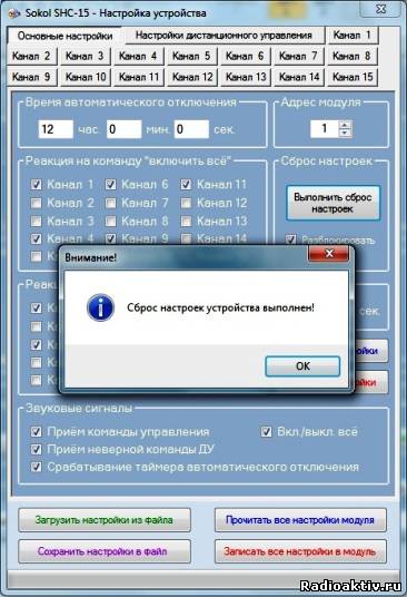
As you can see in the figure, sliders and checkboxes are used to control channels. When you check or uncheck the box, the corresponding channel of the module turns the load on or off. The control program has 100% feedback with the control module, so if the state of the channel changes, then both the “tick” and the regulator in the control window will change their state...
By smoothly moving the slider, you can easily change the brightness value from the minimum to the maximum value (if brightness adjustment for a given channel is allowed in the settings of this channel, see settings below). When changing the brightness of a channel using the remote control or light switches, all changes are automatically displayed on the state of the slider-controller. If you try to move the knob while brightness limitation is on, it will immediately return to within acceptable limits. With a smooth increase and decrease in brightness, the current brightness value will be displayed on the slider of the regulator and it will “run”, displaying a decrease or increase in the output voltage of the channels.
The “On All” and “Off All” buttons clearly perform their assigned functions. However, only those channels that are allowed to “respond” to this action will respond to pressing these buttons (see channel settings below).
The overall brightness of the channels also needs no explanation. Here it is already clear that when you move the slider, the brightness of all channels that are allowed to change brightness in the settings will become equal to the set one.
When changing the brightness settings and channel status (on/off), all changes will be automatically saved in the non-volatile memory of the microcontroller. To save the latter's resource, settings are saved only after 10 seconds have passed after all adjustments have been completed and only for channels operating in trigger mode.
With the “About” button it is clear that there is a license agreement and a little about me...
To connect the device to a computer, you must have a COM or USB port. In the latter case, you will need a USB-COM converter. If the device is connected, the correct COM port number and module address are selected, then checking the “Connecting to device” field will not cause any error, and the channel brightness sliders will take their real position after a second... If there are no virtual or real ports, the message “No ports!” will be displayed in the “select COM port” field, and connecting to the device will become impossible.
The “Select device address” field is intended for the operation of several parallel-connected devices at once on one COM port of a computer, if such a need arises. If several modules are connected in parallel along one line, then simply select “Broadcasting” in the address field. The same trick can be performed for group commands “Turn everything on / Turn everything off” when connecting modules in parallel. In this case, all blocks connected to the current port will respond to the command. To exclude conflict situations You need to be careful with tricks like this. It is easier to run several copies of the program and use different computer ports. However, if you really need to connect the modules in parallel, then it is advisable to take care of optocoupler isolation of the lines or use RS232/RS485 interface converters or similar. The microcontroller and computer programs operate in half-duplex mode, which makes it easy to implement the RS485 hardware interface. You can change the module address in the “Basic settings” field.
For device settings, there is a second window of the control program, called up by clicking the “Settings...” button in the main window. However, pressing this button, as well as any manipulations with the sliders, will be possible only after connecting to the device.

The settings window contains several tabs, each of which contains a number of module settings. Tabs from “Channel 1” to “Channel 15” are intended for settings of the corresponding channels.
Each of these tabs contains settings for the brightness and time of channel activity. To allow channel brightness adjustment, you must check the appropriate box. To enable a smooth increase or decrease in brightness, you need to activate the corresponding option. In the fields, the maximum and minimum brightness speaks for itself... However, to protect against fools, there is a “trick” here too. If you set the minimum brightness value equal to the maximum or greater than the maximum, then brightness adjustment becomes impossible (equivalent to prohibiting brightness adjustment), and the lamp will turn on with the minimum set brightness.
The value in the channel activity time field can range from 0 to 99,999. Please note that one unit entered in the field corresponds to 0.1 seconds of real time. Thus, the channel activity time can be set in the range from 0 to 9,999.9 seconds (from 0 to 2 hours 46 minutes 39.9 seconds). If the value “0” is entered in the field, then this channel operates in trigger mode. If the entered value is different from zero, then when the command is given, the channel will turn on with the specified brightness for a time equal to the entered value divided by 10.
This chip is recommended to be used in conjunction with a smooth decrease in brightness when lighting entrances and staircases, and with low values of activity time and prohibition of brightness adjustment - to control electrified entrance gates and roller shutters...
1. In trigger mode, a short press on the control button will turn the channel on or off, and a long press, with the “brightness adjustment” checkbox selected in the channel settings, will change the brightness level. When the brightness reaches a minimum or maximum value and the “change of direction” checkbox is checked in the channel settings, the direction of brightness change will change. In any case, if you briefly release the button during adjustment and press it again for a long time, the direction will change to the opposite. Those. If the brightness changes in the wrong direction, release it briefly and press the button again.
2. In the pulse operating mode, briefly pressing the control button, remote control button, or checking a “tick” on the computer will turn on the channel, with the brightness set before activating the pulse operating mode.
The “Basic Settings” tab allows you to configure global parameters of the module:
Automatic shutdown time;
- Module address;
- Reaction of channels to the commands “Turn on all” and “Turn off all”;
- Settings sound signals supplied by the module;
- Anti-bounce of the manual control keyboard;
- Perform a general reset of the device...
Now let's talk about everything one by one:
1. The automatic channel shutdown time is the time after which, in the absence of control commands, an internal command equivalent to the “Turn everything off” command will be issued. In this case, all outputs are turned off, the shutdown of which is allowed by the “Turn off all” command (see below). The shutdown time can be from 1 sec. until 17:00 59min. 59sec. When entering zeros in all columns, i.e. 0 hour 0 min. 0 sec. The automatic shutdown timer will not be activated and the channels will therefore not be turned off.
2. Module address – logical address of the control module for identification. Used for parallel connection several devices to one computer COM port.
3. The graphs for setting up the reaction of channels to the commands “Turn on all” and “Turn off all” allow you to select the channel numbers that will respond to these commands. This function is useful to use when leaving home... Just press the button in the hallway and all the lights in the house go out, the roller shutters close, and the sockets and the refrigerators plugged into them work...
4. Configuring the sound signals supplied by the module allows you to select those commands in response to which the module’s beeper will “moo”...
5. In the “Keyboard” section, set the number of polls for manual control buttons (10 ms each) after which it will be considered that the button is briefly pressed. The duration of a long press should be at least twice as long. By changing the set value in the range from 1 to 100, you can also change the “sensitivity” of the keyboard to short presses of the control buttons within 0.1...1.0 seconds. The default value is 20, which corresponds to a polling time of 0.2 seconds.
6. It is imperative to perform a general reset of the device when manufacturing and turning on a new device for the first time. In this case, the default settings will be written to the module’s memory: all “features” and “bells and whistles” are enabled, the trigger mode of operation of all channels is set... The reset procedure is deliberately complicated to protect it from fools: the reset button remains inactive until the “Unblock” field will not be checked. If the reset operation is successful and the module is pre-initialized with new settings, a corresponding message will be displayed, but if it fails, then another...

The “Remote control settings” tab allows you to configure this very remote control, i.e. response to remote control buttons...
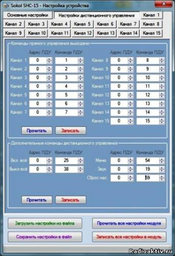
The settings field consists of two blocks: “Direct output control commands” and “Additional remote control commands”. Everything is simple here: we want to look and change the addresses or assignment of the remote control buttons - we read the settings, change and write the already modified ones to the module...
Now about the “biggest buttons”. They are located at the bottom of the Device Setup panel, under the settings tabs. These four mysterious rectangles do what they actually say: Read and write ALL (!) module settings at once and save or load these settings into the control program from a settings file with the extension “*.shcm”. The status bar below the buttons shows the progress of these operations. Since there are many settings, and, therefore, these operations require the transfer of a fairly impressive amount of information between the module and the computer, the process lasts several seconds. Before clicking the red “Write all module settings” button, make sure that on all tabs you have made exactly the settings that you need. Otherwise you will have to reconfigure...
The performance of the control program has been tested in operating systems Windows XP SP2 x32, Windows XP SP2 x64, Windows XP SP3 x32, Windows Vista x32, Windows Seven x32, Windows Seven x64. For normal operation The program requires administrator rights on the computer and Microsoft Net Framework v3.5 or higher installed.
Now about those module settings that can be performed without a computer using only a remote control.
First of all, this is “training” the module in remote control commands, i.e. recording remote control codes into memory, similar to the “Remote control settings” tab of the Sokol SHC-15 Terminal program. To enter the “learning” mode, you need to turn off the power to the module, if it is on, and wait 20-30 seconds until the power filter capacitors are discharged. After that, you need to press a button on the remote control, preferably the one that will later be responsible for controlling the first channel of the module, point the remote control at the photodetector and supply power to the device. One long beep will sound. The remote control button must be continuously held until the second beep starts sounding (about 10 seconds), after which the module will give another long beep and go into the “learning” mode. While the second long signal is sounding, you will still have time (0.5 seconds) to release the remote control button if you suddenly change your mind and decide to assign another remote control key to control the first channel of the module. Next, you need to sequentially press the remote control buttons in the following order:
1. Control of the 1st channel of the module;
2. Control of the 2nd channel of the module;
………………………………………
15. Control of the 15th channel of the module;
16. Enable all channels allowed for inclusion;
17. Turn off all channels that are allowed to be turned off;
18. Entering the system menu;
19. Sound control;
20. Reset module settings to default.
After pressing each of the buttons, the microprocessor stores the code corresponding to the pressed key in non-volatile memory and emits a short low-tone beep. When you press a button whose code has already been stored in memory (the button was pressed previously or is currently being held down), the device emits three short high-pitch beeps, indicating an error. At the end of the memorization procedure, three short low-tone beeps will sound, and the device will go into operating mode, in which channels are controlled.
Now you can do a hard reset. To do this, press the previously programmed “Menu” button on the remote control. In this case, the device will emit a low-pitched beep, indicating entry into the system menu. While in this very menu, we then press the button on the remote control that corresponds to the previously programmed command “reset module settings to default”, and in response we receive three short low-tone signals confirming that the settings have been reset.
While in the hardware settings menu, you can also configure the sound signals generated by the module. To do this, while in the menu, you need to press the “sound control” button on the remote control and after a long high-tone signal, press one of the channel control buttons on the remote control:
To turn off all sound signals, press the “Control the 1st channel of the module” button;
To turn on all sound signals except signals for receiving an incorrect command, press the “Control the 2nd channel of the module” button;
To turn on only the sound signal confirming receipt of the correct command, press the “Control the 3rd channel of the module” button;
To turn on all sound signals (reception of any command, including incorrect ones, from the remote control and keyboard, activation of the automatic shutdown timer), press the “Control the 4th channel of the module” button.
The device signals the completion of the operation with two short high-pitched beeps. Please note that the capabilities of the Sokol SHC-15 Terminal configuration program in terms of setting up sound signals are much wider than directly setting up sound signals through the module’s hardware menu.
To exit the hardware settings menu, you must press the “Menu” button on the remote control again. After two long low-tone beeps, you can control the channels and lights again... If you do not “exit” the menu within 30 seconds, the “exit” will occur automatically.
Now a little about practical application various operating modes of the device:
To control sockets that include any electrical appliances except incandescent lamps (or other lamps designed to work together with dimmers, they are also called dimmable), it is advisable to set the minimum brightness value in the channel settings window to 50 (maximum value), the same applies to maximum brightness. After this, you should disable the brightness adjustment of the channel that controls the sockets, and disable the smooth increase and decrease in brightness.
To control lighting lamps on stairwells, in storerooms, in hallways, etc. you should switch the corresponding channel to temporary activity mode by entering the activity time in seconds multiplied by 10 into the settings field and select the required brightness, and if necessary, then a smooth increase and decrease in brightness. After pressing the remote control button or control switch, the lamp will light up for the set time (smoothly, if the corresponding option is enabled), and then go off (again, smoothly, if enabled).
To control roller shutters and garage and other entrance gates, it is advisable to set the channel activity time equal to or slightly longer (if the roller shutters and gates are equipped with limit switches) to the full opening/closing time. If it is necessary to partially open roller shutters or gates, then you should set a short activity time of 0.3 - 0.5 seconds. Then the actuator will only work while the button is held down. The brightness controls should be turned off as described above for sockets.
To control lamps in dimming mode, no special settings are required. The main thing is to set the channel active time to zero or reset the settings to default. The remaining settings (decrease and increase in brightness, minimum and maximum brightness, etc.) are for your taste and color.
When choosing a remote control, it is necessary to take into account that a prerequisite is that it operates using the RC-5 protocol. It is also necessary that the number of generated code messages be at least 20. It must be remembered that the presence of, for example, 40 control buttons does not guarantee. that the remote control can issue 40 different commands. Many buttons on modern remote controls are duplicated and, although they have different labels, inside the remote control they are electrically connected in parallel (for example, “-/--” and “<= » в пульте RC6).

It is advisable to use a remote control with a system address other than zero, unless, of course, readers who have repeated the design want to control the device simultaneously with the TV or entrust their house to a neighbor who, by switching channels, will “play” with your lighting.
There are many universal remote controls on sale in which you can select the address of the controlled device. For example, remote controls of the RC6-2...RC6-5 series, widely used in conjunction with sixth-generation HORIZONT TVs, change the device address from “0” to “5” when the “VCR” key is pressed together with the control buttons. This circumstance allows you to use remote controls from the RC6-2...RC6-5 series, which have 42 buttons and generate 40 control commands, both to control the TV and the described device, excluding mutual influence.
The ideal option is to subsequently rework the remote control, which will allow you to change the transmitted address or switch it. In the RC6-5 remote control this is achieved by simply short-circuiting the button that changes the address.
Since it is possible to program the activation of outputs from different remote controls (for example, control of outputs 1...10 from one remote control, and control of outputs 11...15 and service functions from a remote control with a different system address), each of the remote controls only controls “your” exits, this opportunity should also not be neglected. As an option, it is possible to use one remote control with a small number of buttons, but a switchable system address (usually the “Shift” key is used in imported remote controls for these purposes). If there is no switch, you can install it yourself.
A demo version of the microprocessor firmware, in hex format, can be downloaded from the link at the bottom of the article. The only limitation of the demo version is the lack of saving settings in the device’s non-volatile memory and in a file in the PC control program. That is, if there is a power failure in the network or the power is turned off, all module settings will have to be done again;-)
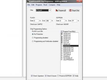
How the Fuse bits of the controller should be programmed for the ATMega8, ATMega8A, ATMega8L microcontrollers is shown in the figure :

Download links:
DIY remote control of a chandelier
Once upon a time, I saw a chandelier in a store that was controlled by a remote control. And I wanted to control the lighting in the room while lying on the sofa, especially in the evening, when I didn’t want to get up and go to the switch. After some time, GOOGLED the Internet and found many different schemes, but this one suited me the most, because... there were also ATTINY45, and triacs, and other small things. I also liked in the author’s article that you can use energy-saving lamps. Having estimated and drawn the board, I assembled the device without changes. When flashing the controller, it turned out that the article did not indicate “FUSES”. After some thought, I sketched out the circuit in Proteus, calculated the placement of fuses, flashed the controller and the device started working immediately. I played around with the remote control and decided to check how it would work with energy-saving lamps.
Having changed incandescent lamps to energy-saving ones, the first time I turned them on, I successfully burned a couple of seven-storied lamps. Having thought a little, I reduced the resistors R9, R10 and replaced the semistors, I began the destruction test, successfully destroyed a couple more, and stopped. Because I haven’t mastered writing programs for microcontrollers yet, so I decided to change the circuit a little.
Here's what happened: remove the one circled in red, add the blue one.
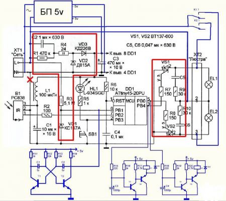
The need for network frequency pulses has not disappeared; without them, the circuit will not work (since, according to the firmware at the output, the controller controls triacs, and they, in turn, require pulse control). To galvanically isolate the controller from a 220-volt network, we add a simple multivibrator with two transistors, which will simulate network pulses with a multivibrator pulse frequency of about 70 Hz.
The output stages for turning on the relay are the same; we assemble them on two transistors.
About the elements used:
PSU is a 5 volt mobile phone charger unit, you can use small UC30D-2 transformers for 6 or 9 volts, its dimensions are 32mm*27mm*15mm, where 15 mm is the height. Not forgetting about the diode bridge, capacitors and stabilizer 7805.
T1, T2 - any low-power npn soldered from a faulty motherboard.
C1, C2 - at first I installed polar ones, but then I looked at SMD ones soldered from a faulty motherboard (there are a lot of them).
T3, T5 – BC817 (SMD, because they take up less space)
T4, T6 – BC807 (SMD, because they take up less space)
VD1, VD2 – KD521 (whichever ones were on hand)
K1, K2 - JZC-6F (5V) or HK4100 1Z (5V).
I tried different IR receivers: at 36 kHz and at 38 kHz - they work equally stably (TSOP4836 is better), but it is necessary to take into account the illumination of the receiver by lamps, it would be ideal to place glass in front of the receiver that is transparent in the IR region of the spectrum, or to place the receiver closer to the base of the chandelier .
The archive contains boards for the original circuit, for the JZC-6F relay, for the HK4100 1Z relay.
Fuses:
Photos of boards:

The control circuit along with the power supply easily fit into the base of the chandelier. I drilled three holes: for the LED, the button and the IR receiver, fixing them with hot glue (if you wish, you can not install the button, I set the R5 resistor to 2 kOhm so that there is less light at night).
It is worth adding that the scheme has been operating continuously for several months. Thank you for your attention…
Archive with boards, schematics, firmware and fuses.
Conveniently open garage doors without leaving your car. To achieve this opportunity, the gates are equipped with a remote control system. You can entrust this task to specialists, but with some skills you can organize remote control yourself. You can also install ready-made modules yourself.
When not to install automation
You should not make automation in unguarded garages or where there are frequent power outages. A de-energized gate will be easy for an intruder to open, so in this case it is necessary to install additional locks. But then you still have to get out of the car to open them, and remote control becomes meaningless.
The disadvantages of automatic gates include the fact that you will not open them if you forgot the remote control, the battery in the remote control is dead, or the antenna is broken. However, there are models that can be opened manually if the automation malfunctions.
Types of gates
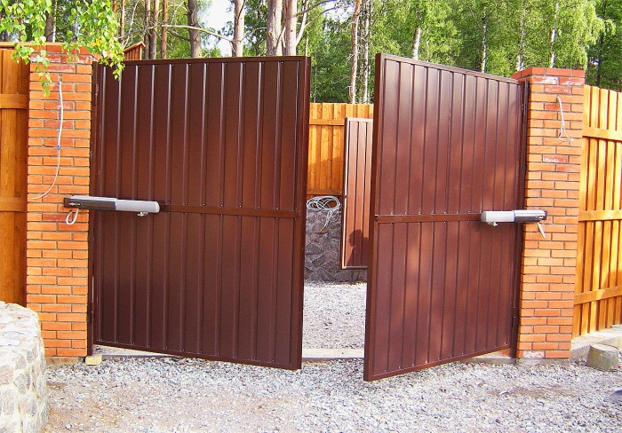
For swing gates, at least 4 photocells are required, which will stop the movement of the leaves if interference is detected between them. Two of them should be installed on the gate posts, and two - on separately located posts at the maximum opening distance. To move them, two drives are needed.
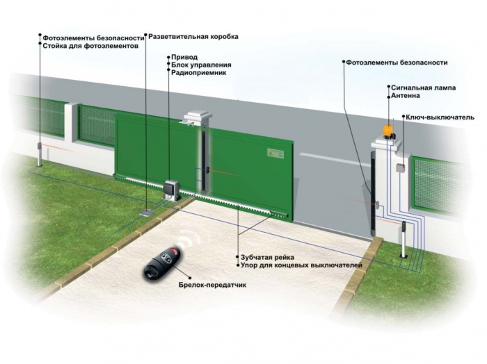
Sliding gates are safer in this regard. They require only one drive and two photocells. However, in practice this type is rarely found in private garages, since they are more difficult to maintain, the mechanism breaks more easily, they can warp or begin to jam, and they also take up a lot of space. In winter, you will need to regularly clean the rails to prevent icing. Swing systems are more durable and reliable.
For swing gates, when you press a button on the remote control, a signal is sent simultaneously to both drives, and the gate begins to open or close. Additionally, they make it possible to remove the lock so that if necessary (for example, in the absence of electricity), you can open the gate by hand.
The control system for sliding garage doors is simpler and, as a rule, is made in one housing, which contains both the drive and the control unit.
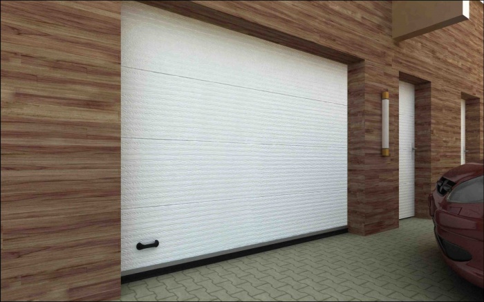
Sectional and roller shutter models are most often automated. It is for them that there are many drive options on sale; for swing and sliding ones there are fewer of them. Often such gates are already sold with a remote control system.
Remote control system design
Whatever the gate design, the automation includes the following elements:
- electric drive,
- control system,
- remote controller
- security system (sensors, photocells).
Sectional and roller garage doors have drives located on the ceiling. Such gates are already sold with a remote control system; all that remains is to connect them correctly.
![]()
The electric drive is the part that directly moves the shutters. This can be a chain or lever drive such as a jack. To move the shutters, install an electric motor with a power of 200-400 W, connect it through a transformer that reduces the voltage to 24 V or directly to a 220 V network. When purchasing a motor, pay attention to the materials from which it is made. Many Chinese models, for example, have plastic gears that cannot last long. All moving and rubbing parts must be metal.
Important! The gate must move easily, otherwise the drive will quickly break.
To connect automatic gate remote control, use a three-core cable with a length of no more than 50 m and a cross-section of at least 1.5 * 3 mm. Cable brands are suitable. It is laid along supports or in the ground in a polyethylene tube at a depth of at least 40, and preferably 70 cm. A cable is run from the control unit to the signal lamp and antenna.
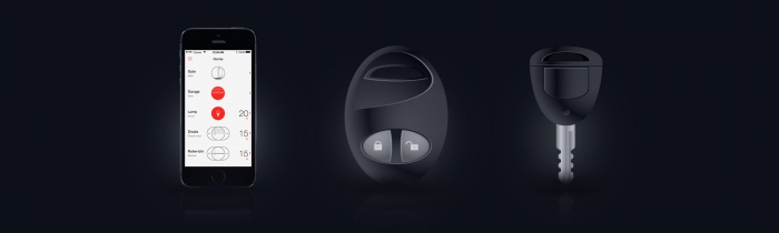
To remotely control the gate, a radio key fob with two buttons is used. One is responsible for opening and closing, and the second is for lighting. You can also install a module that is controlled from a mobile phone, sometimes this is more convenient, since you always have your phone with you and it’s easy to forget the key fob. To open the gate without a key fob or phone, an unlocking system is provided. It will also help open the gate if it turns out to be de-energized.
How to make a remote control system with your own hands
The easiest way is to buy a ready-made system and install it. At the same time, if you know how to work with electronics, you can make a remote control for your garage door yourself. To do this, you need any inexpensive device with a remote control: a bell, a car door lock, a car alarm.
You can use remote control modules, for example MP325M.
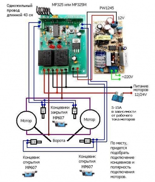
To supply power in this circuit, a PW1245 converter was used. You can also use a step-down stabilizer based on a single chip. However, the converter with its own separate power supply makes the entire system more reliable.
MP607 sensors were used as limit switches (gate status indicators, whether they are open or closed). This sensor has two groups of contacts. One of them is normally closed, the other is normally open. In this circuit, a normally open circuit was used for connection.
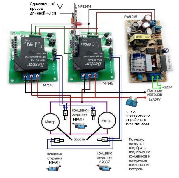
The MP325M module can be used in temperatures down to -15 degrees, so it is not suitable for use outdoors in winter. To operate the remote control at temperatures down to -40 degrees, you can replace it with the MP324M module with MP146 base units. The diagram is shown in the figure.
A single-core wire 43 cm long is an antenna. The length of the wire was selected based on the requirement that the gate open from the required distance. To select the length of the antenna to open from the distance required in your case, you first need to take a longer wire and select the desired length by gradually cutting it. It is best to place the antenna vertically above the gate. The antenna must not be bent, twisted, or placed in metal casings.
Connecting a finished control unit
If you purchased a ready-made control unit, you need to connect it, and you need to do it correctly. The signal lamp and antenna have only two or three wires: phase and neutral and sometimes ground. There are more wires on the block itself, there are wires for connection
- antennas,
- lamps,
- driving drives,
- photocells,
- programmer for configuration,
- in some cases - additional lighting; there is also a power cable.
The connection diagram of the control unit may be as shown in the figure.

- Contacts 1 and 2 are intended for connecting an external antenna.
- Contacts 3-6 are intended for connecting a keyboard from which system settings are configured.
- A beacon is connected to pins 7 8.
- To contacts 9-10 - one or two drives,
- To contacts 11-12 there are photocells.
- Contacts 13 and 14 are intended for connecting an additional lighting lamp.
- 15-17 are intended for connecting the power supply: 15 - zero, 16 - phase, 17 - ground.
The control unit is placed in a dust- and moisture-proof casing, the degree of protection of which must be at least IP 54 (complete protection from dust, protection from splashing water).
After a long power outage, the gate may not open. Then you will need to restart the system. Some of them have a battery, some have memory. Features of a specific model must be clarified with the seller.
Remote control of garage doors is very convenient, but it also has its disadvantages. Now you can install a remote control system on a gate of any design; for this you need to buy a ready-made system or, if you are knowledgeable in electronics, make it yourself.
The considered circuits are intended for remote control of loads via telephone wire line, mobile and radio communication channels, as well as control of various devices using an infrared channel.
The infrared control device consists of two blocks - a transmitter and a receiver with a possible range of up to seven meters. The remote control circuit is built using a PIC12F629 microcontroller, the firmware of which you can download from the green arrow just above.

The basis of the IR transmitter circuit is the PIC12F629 microcontroller; for its correct operation using the RC5 protocol, a stable carrier frequency of 36 kHz is needed, so the design uses an external generator on radio components Q1, C1, C2.

The modulated IR signal from the transmitter is sent to the TSOP4836 receiving module and processed by the PIC12F629 in accordance with the firmware. Depending on the button pressed in the transmitter circuit, the desired channel in the receiver is activated. Relays switch the load on each channel. To flash microcontroller firmware, use .

It is quite easy to make an attachment for almost any radio call to control any household appliance. The modification allows you to remotely turn on and off a household appliance, the power circuit of which contains relay contacts
On this page I have collected simple and easy-to-repeat schemes for remote control of loads on microcontrollers, for example lighting or any household appliances. You can find firmware and other additional files for projects here.
The considered circuits provide remote control of the load. Both designs have a programming function, which makes it possible by pressing a programmed button to turn on or off various loads at a distance
The schematic diagram of the transmitter is shown in Figure 1. SW1 is a module of eight DIP switches. It is installed on the board and allows you to set an individual code - an eight-bit binary number. The receiver must be set to exactly the same code, otherwise it will not respond to commands from this transmitter. Instead of a block of DIP switches, you can wire ordinary wire jumpers, but, again, the wiring must match the wiring of the jumpers on the receiving unit
The circuit is powered by a 5V power supply. The CD4017 digital microassembly is a typical counter divider by 10. The received signal from the sensor is sent to the microcircuit, in accordance with the signal at the outputs Q0-Q9, a high state is set; in our circuit example, a relay is connected to the Q1 output through a bipolar transistor T2. Almost any load can be connected to a high-voltage circuit - from a regular iron or microwave to a refrigerator or air conditioner

The illuminated Status LED indicates that the signal has been received and the relay has activated. Even any TV remote control can be used as a remote control. Appearance of the assembled device on a breadboard:

In this article we will talk about how to assemble IR load control with your own hands. The control circuit can control various loads connected to it: lights, fans, household appliances. IR control is carried out using any remote control, including television.
In the first scheme considered, the fan or cooler is controlled by a thermistor signal during a specified time interval. The amateur radio design is very simple, as it is assembled using only three bipolar transistors. Such control systems can be used in a wide variety of applications where cooling with a fan is required, for example, cooling a computer motherboard, in powerful audio amplifiers and power supplies and similar devices that can overheat during operation.