IR receiver "TSOP" - Reference materials - Theory. Infrared alarm sensor
Signal for controlling a digital camera using an iPhone, iPod and other “high-quality” mobile audio playback devices. Apple owners portable devices can purchase a ready-made IR transmitter and DSLR.Bot program for remote control camera (and a lot of other useful functions) for less money than the simplest specialized IR control panel costs. Since I have a smartphone of a different brand, I tried to implement the idea for it.
The idea is that a good audio file player can generate a signal with a frequency of 16-19 kHz. And if you send two such signals “toward” (with a phase shift of half a period), you will get a carrier for the IR control channel, which usually uses frequencies of 32-38 kHz. Such sound signal 16-19 kHz and its modulation are easy to generate in a sound editor. A mobile player that supports WAV/MP3 files is suitable for playback (MP3, as practice shows, is less suitable for storing IR control signals). As a transmitter, you need to use IR LEDs, connecting them to the headphone output of the player, to the left and right channels, “towards” each other. The LEDs will open with a main carrier frequency of 16-19 kHz, and since the signal in the two stereo channels is shifted by half a cycle, the "total" flicker carrier will be 32-38 kHz.
Diagram for connecting IR LEDs to a stereo connector. My smartphone recognizes headphones automatically and does not do this if there is “nothing” at ground, so I additionally added two 4.7 kOhm resistors to the circuit (with a higher resistance, the smartphone stops recognizing the headphones, and I needed the maximum possible resistance to ensure minimum leakage current from the main channel of the stereo signal “left-right” for LEDs).
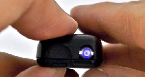
The creation of an IR transmitter is only the first stage in the implementation of remote camera control. You also need to generate a signal and come up with a control algorithm. In my case of Canon SLR cameras, the signal should imitate the signals of the Canon RC-1 remote control.
Remote control Canon RC-1. Has a mode switch. In the first position there is a normal release, in the second - with a preliminary two-second delay.
The description of the IR signal of the Canon RC-1 remote control, which I found on the Internet, did not help to make a stable operating remote control using IR LEDs. Neither the smartphone nor the multimedia players I use would launch the camera. But it was possible to control the camera from a computer. It is extremely difficult to understand why this is so without being able to observe the IR signal. You can determine that IR LEDs are working in principle using a digital camera, which, unlike the human eye, sees the IR signal.
A digital camera “makes” the IR signal visible by mistakenly transmitting the signal from the invisible region of the spectrum to the visible (which is partly why photographs of many digital cameras, especially compacts, do not reproduce colors and brightness correctly).
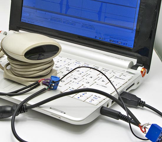
However, without “tools” it is impossible to determine why the LED that is shining still does not start the camera, and I did not have an oscilloscope that records a signal with a frequency of 30-40 kHz. I had to use the idea described in the article “Sound card as an element of an optical-electronic measuring device”, connecting an IR sensor as a receiver.
The sound card does not allow recording a signal in the range of 30-40 kHz, but only its modulation. It is known that the fill signal in the IR channel of the Canon camera control system lies in the range of 30-40 kHz, which allows the sound card to distinguish the modulations of this signal with great accuracy (on the order of the carrier period). Ignorance of the exact carrier parameters is not big problem. In the end, you can make a trigger signal with a carrier of 30, 32, 34, 36... kHz and select the appropriate one. There won't be many options.
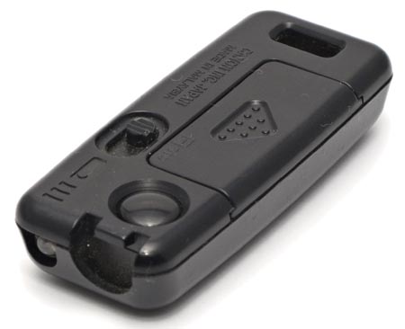
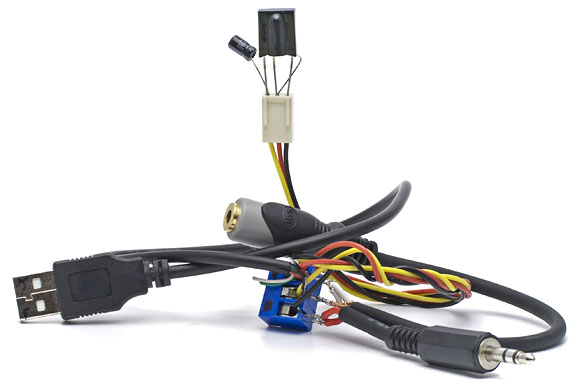
To receive an IR signal to a sound card, you need a special sensor. I adapted the IR remote control sensor from an old TV tuner for this:
The IR receiver is connected to the computer (TV tuner expansion card) via a standard stereo connector. But this does not mean that you can simply insert it into a sound card and record a signal from it. Inside the receiver is a simple circuit consisting of an IR sensor, a capacitor and a resistor (similar to the one shown later in the text). The receiver's IR sensor has three pins: two power and a signal. For the receiver to work, it must be powered by applying voltage to the corresponding terminals. Let's take power from the computer's USB port:
For the sake of “versatility” of the article, I assembled an IR receiver based on the quite common TSOP 1736 IR sensor (the last two digits in the marking are the optimal carrier frequency for the sensor in kHz; another sensor from the TSOP 1730-1740 series is probably suitable). The connection diagram is as follows:
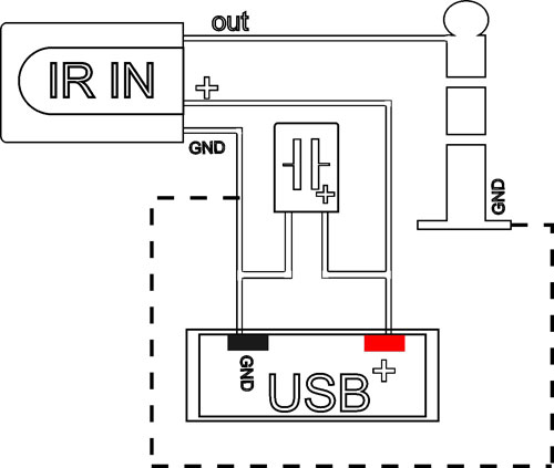
Standard connection diagram for an IR receiver. In the diagram, the IR IN sensor is connected to a stereo connector (for connecting to the microphone input of a sound card) and powered by USB. The dotted line shows the ground bus, which is generally optional when connecting to one computer. The capacitance of the polar capacitor is 4.7 μF, voltage 5 V. A resistance of 50-100 ohms can be installed in the power circuit to limit the current.
To test the suitability of electronic components, a simple IR receiver can be assembled without soldering. However, in this version, the signal transmitted to the recorder may not be clear enough, which will make decoding difficult. Therefore, after testing on a breadboard, it is better to carefully solder the components.
The IR receiver does not have to be used in conjunction with a computer. The IR signal will be recorded by a more or less high-quality voice recorder for subsequent decoding. I used Alesis PalmTrack, which, according to the specification, supports 48 kHz WAV files in recording mode. This inexpensive voice recorder has high (claimed) characteristics and often various reviews Recommended as a recording device when shooting movies with digital SLRs. I have not yet assessed it as very high quality, but the price of the voice recorder is really low (when delivered from abroad).
![]()
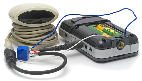
Connecting the IR receiver to the voice recorder. The signal output of the IR receiver must be connected to one of the recording channels of the voice recorder, and the power must be taken from the batteries (I first checked that the “0” power supply and ground on the stereo connector are connected to the common bus).
A freely distributed program (license) is suitable for signal processing. It can receive a signal from a sound card and immediately digitize it or work with separately recorded sound files. My program did not always see the IR receiver connected to the sound card. To get around this feature, you can run the program with a normal microphone connected, and then connect an IR receiver instead. For digitization, it is better to select the maximum supported sampling rate (96 kHz).
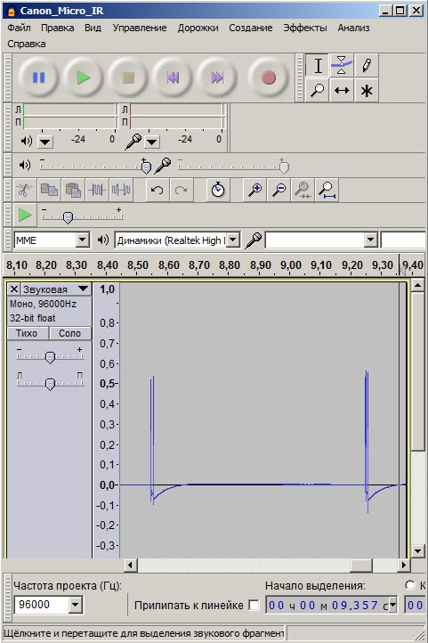
This is what the IR signals from a Canon RC-1 remote control sequentially recorded using Audacity look like. The first signal of the two more widely spaced peaks is a normal shutter release, the second is a shutter release with a preliminary two-second pause.
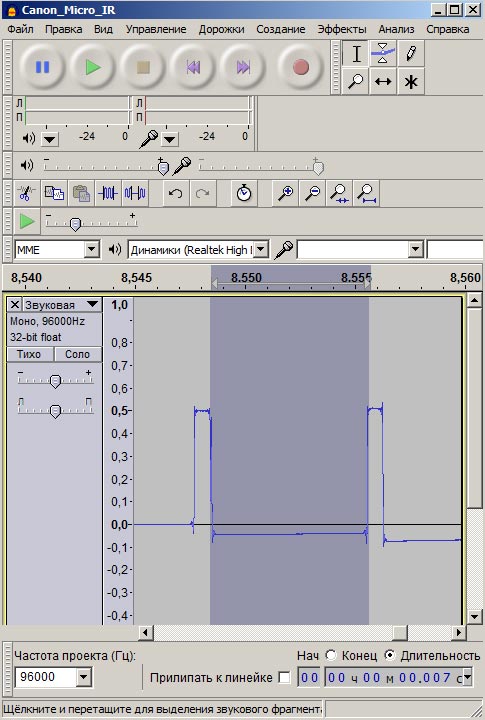
When you zoom in on the time scale, you can see a more or less accurate “description” of the signal modulation. It consists of two consecutive pulses and a pause. The duration of the pause is approximately 7 ms. The duration of pulses and pauses can be more accurately determined by the number of samples and sampling frequency.
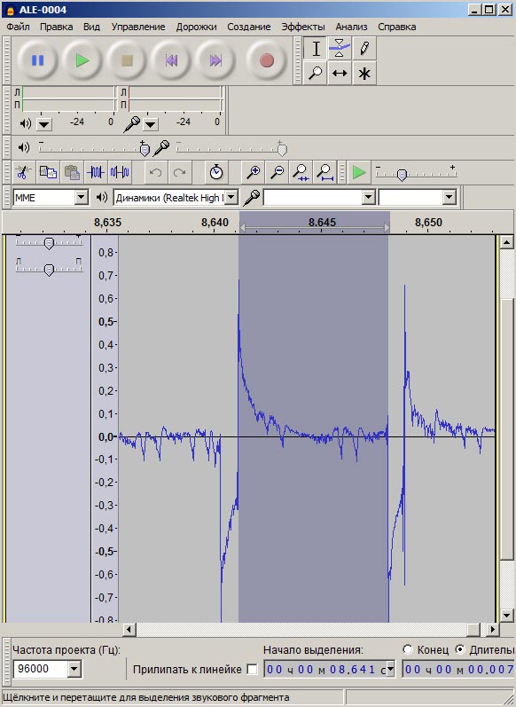
“Decoding” of the Canon IR remote control signal, recorded using Alesis PalmTrack. Knowing in advance how the signal is roughly structured, you can use a voice recorder to obtain the necessary data to decrypt it.
Using existing hardware for my Canon RC-1 remote control, I obtained the following signal structure data (based on several sequential recordings). Normal shutter release: pulse 64-72 samples (when digitized at 96 kHz) - pause 670-680 samples - pulse 64-72. Release the shutter with a preliminary pause of 2 seconds: pulse 64-72 samples - pause 480-490 samples - pulse 64-72. Converted to seconds, we get for a normal shutter release: ≈0.7 ms - 7 ms - 0.7 ms. For delayed release: ≈0.7 ms - 5 ms - 0.7 ms.
The next part will describe how to generate a signal and “tailor” it to the playback device.
First, let's clarify the names a little. The abbreviation TSOP in electronics can indicate the type of chip package (Fig. 1 "1"). (TSOP - Thin Small-Outline Package) as well as TSOP is the name of a family of sensors for receiving infrared signals (Fig. 1 "2").
It is this infrared radiation receiver that we will further refer to as TSOP. (TSOP - Temic Semiconductors Opto Electronics Photo Modules).
A little history.
Already in the 1960s, the first Appliances, televisions and radios, with remote control. At first, control took place via wires, then remote controls with light or ultrasonic control appeared. These were already the first “real” wireless remote controls. But due to sound or light interference, the TV could turn on or change channels on its own.
With the advent of inexpensive Infrared LEDs in the 1970s, it became possible to transmit signals using infrared (IR) light, which is invisible to humans. And the use of modulated IR signals made it possible to achieve very high noise immunity and increase the number of transmitted commands.
Signal modulation- the process of changing one signal (carrier) in accordance with the shape of another signal (original).
An IR photodiode or an IR phototransistor is usually used as an IR radiation receiving element. The signal from such a photocell must be amplified and demodulated.
Signal demodulation- the process of isolating the original signal from the carrier background.
Since the photodiode, amplifier and demodulator are an integral part of the IR receiver, these parts began to be combined in one package. The case itself is made of plastic that transmits infrared rays. Thus, over time, the well-known TSOP infrared signal receiver was created, which is used in 99% of all household equipment for remote control.
Types of TSOP receivers.
Since integrated IR receivers were produced in different “eras” and by different companies, there are many of them external views. The main types of housings are shown in the figure below:
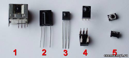
1) IR receiver from SHARP. Designation GP1Uxxx. Inside the tin shell there is a small printed circuit board with IR photodiode and microcircuit. Such a photodetector can be found on the boards of old TVs and VCRs.
2) In this case, IR receivers are most common. They were produced back in the mid-1999s by Telefunken with the designation TFMSxxx. Now they are produced by Vishai, among others, and are designated TSOP1xxx.
3) IR receiver in a smaller body. Marked as TSOP48xx, ILOP48xx, TK18xx.
4) A very rare IR receiver housing. Previously produced by Sanyo. Designated as SPS440-x.
5) IR photodetector in SMD case from Vishai. Designation: TSOP62xx.
("x" in the notation means a number or letter.)
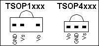
The pinout of each type of TSOP, as usual, can be found in the corresponding documentation for the specific brand of IR receiver. Please note that IR receivers numbers 2 and 3 have different pinouts! (Fig. 3):
Vo- IR receiver output pin.
GND- common output (minus power supply).
Vs- positive supply voltage output, usually from 4.5 to 5.5 volts.
Principle of operation.
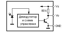
A simplified block diagram of a TSOP receiver is shown in the figure below. The output element inside TSOP is regular N-P-N transistor. In the inactive state, the transistor is closed and there is a weak level at the Vo pin high voltage(log "1"). When infrared radiation with a “fundamental” frequency appears in the sensitive zone of the TSOP, this transistor opens and the output pin Vo receives a low signal level (log. “0”).
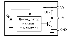
The "fundamental" frequency is the frequency of the infrared radiation (light) pulses that the internal TSOP demodulator filters out. This frequency is usually 36, 38, 40 kHz, but it can be different; you need to find out about this in the datasheet for the specific type of TSOP receiver. To increase the noise immunity of the IR communication channel, modulated transmission of IR light is used. The timing characteristics of modulation for anti-interference transmission are given in the datasheet for a specific TSOP receiver. But in most cases it is enough to follow simple rules:
1)
minimum number of pulses in a pack - 15
2)
maximum number of pulses in a pack - 50
3)
minimum time between packs - 15*T
4)
the pulse frequency in the burst must correspond to the main frequency of the TSOP receiver
5)
The LED must have a wavelength = 950 nm.
"T" - period of the “main” frequency of the TSOP receiver.
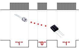
The principle of impulse transmission (figure).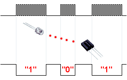
By adjusting the length of the pulse burst within certain limits, binary signals can be transmitted. A long pulse at the output of a TSOP receiver can mean “one”, and a short pulse can mean “zero”. Thus, subject to modulation rules, the transmission range of digital signals in the line of sight between the LED and the TSOP receiver can reach 10-20 meters. The transmission speed is not high, about 1200 bits per second, depending on the TSOP receiver used.
Using TSOP as a sensor
.
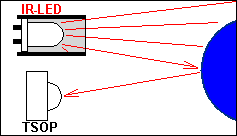
TSOP receivers can be used as other types of sensors.1) The sensor is “transmission”, the object prevents IR rays from the source to the receiver.
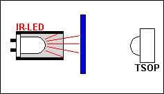
2) “Reflection” sensor, the reflection of IR rays from an object is detected.
The infrared spectrum of light, like visible light, obeys the laws of optics:
- radiation can be reflected from various surfaces
- radiation intensity decreases with increasing distance from the source
These two features are used to build so-called “IR bumpers” - contactless obstacle detection sensors. To eliminate false alarms or false non-operations of such bumpers, it is necessary to emit bursts of pulses, as when transmitting commands from the control panel.
Pulse trains can be generated using conventional logic chips or a microcontroller. If the design uses multiple sensors based on TSOP receivers or multiple emitting diodes, selective polling of the sensor “triggering” should be provided. This selectivity is achieved by checking the response of the TSOP receiver only at the moment when a packet of IR pulses intended only for it is transmitted, or immediately after its transmission.
The triggering distance of the IR bumper based on the TSOP receiver can be adjusted in three ways:
1)
changing the fundamental frequency of IR radiation pulses,
2)
changing the duty cycle of the fundamental frequency of IR light pulses
3)
by changing the current through the IR LED.
The choice of method is determined by the ease of use in a particular IR bumper circuit.
Contactless bumpers based on TSOP receivers have a significant drawback: the “operation” distance of such a bumper greatly depends on the color and roughness of the reflective surface of the object. But very low price TSOP receivers and their ease of use are of great interest to novice electronics engineers for building a variety of sensors.
Almost every apartment has a radio point, and we were lucky in general - there was a whole radio wiring not only to the kitchen, but also to every room. We haven’t used the radio network for a long time, and several years ago we wrote a request to have it turned off. Thus, quite normal low-power, low-voltage wiring remained in each room and kitchen. And recently a satellite system was installed. What connection? As it turned out, the most direct. Since there is only one receiver, and there are several TVs, and they are located, of course, in different rooms. Of course, there is a cable in the plinth through which the signal is routed. But, there is a need to control the receiver not only in the room where it is located, but also in another, where there is a TV. The signal from the remote control does not pass through the wall and a repeater is needed. At first there was an idea to lay additional wires in cable channel baseboard, in the same place where the television cable is laid. But then we remembered about the radio wiring.
The schematic diagram of the repeater is shown in the figure in the text. Here is an option for three signal reception locations and one output. Each receiving node consists of an integrated photodetector and a transistor cascade. Power and signal come through the same two-wire line.
The operation of the receiving node can be considered using the example of the first of them. Voltage is applied to the communication line 6v through resistor r 5, which increases the resistance of the power supply to 1 kOhm. In the absence of a control signal, the current from the line through the diode vd 1 enters capacitor C1 and charges it to voltage 5-6v. When receiving a signal from the remote control at the output f 1 impulses appearwhich come through a resistor r 1 to the base of the transistor vt 1. With each pulse, this transistor opens and closes the radio wiring. The voltage in it drops almost to zero. But the power supply of the photodetector is underis supported by capacitor C1, since the diode vd 1 does not allow it to discharge through an open transistor vt 1. And in the pauses between pulses, C1 is rechargedthrough an opening diode vdl.
Ultimately on the resistor r 5 there will be logic level pulses. The remote control emits commands modulated by pulses with a frequency of 36 kHz, and the photoreceiver demodulates them, so the resistor r 5 there will be command pulses without modulation. In order to transmit them to the receiver's photodetector, they must first be modulated with a signal with a frequency of 36 kHz, and then sent to an infrared LED. The modulator is made on a microcircuit d 1. Multivibrator on elements d 1.1 and d 1.2 generates pulses with a frequency of 36 kHz. Frequency depends on chain r 4-c 4, and if necessary, it can be easily changed in any direction. Then these pulses are sent to the modulator, which is made on a logical element d 1.3. It also receives command pulses from the resistor r 5. And at its output there will be already modulated pulses, only inverted. To a transistor switch vt 4 they come through an additional inverter d 1.4. Key cascade on vt 4 and infrared LED hl 1 gives an IR signal significantly weaker than any standard remote control, and therefore reliable reception is possible only from a short distance - no more than one or two meters. In this case it does not matter, since hl 1 located at a very short distance from the receiver.
The power source is a network unit from a gaming set-top box like “Dandy” that has played its role. Until 6 v the voltage is reduced by the integrated stabilizer A1.
Details can be very diverse. You can use other photodetectors, but be sure to use the same frequency as the control panel. It is possible to use other transistors, diodes, and IR LEDs.
The receiving units are very simple - only five parts each, so I didn’t make boards for them - I soldered everything on the terminals of the capacitor and photodetector. I actually placed two blocks in radio sockets, since they were in a visible place. This is not at all difficult to do - one contact is removed from the socket and the photodetector “looks” into its hole. And the entire “spider” is attached to the second contact. For one receiver, I had to make a separate case from film packaging and connect it to a radio socket with a wire. I had to do this because the outlet was behind the cabinet.
The transmitting unit is assembled in a similar way, but in the body of a broken remote control from an old TV. This is where the IR LED comes from.
Before you connect everything to the radio wiring, you need to decide on the polarity. The wire there is twisted and the contacts of different sockets do not match. Therefore, you must first connect the transmitting node, and then use a multimeter to determine the polarity of the voltage in other outlets. It is advisable to sign the plus and minus on the sockets, for example, with a felt-tip pen for CDs.
In general, no adjustment was required. Everything worked after the first turn on. Maybe if it turns out that your photodetectors are of a different type and consume more current, and the voltage on them is lower 5v, then you can try to fix it by reducing the resistance r 5. You may also need to adjust the multivibrator frequency (by selecting r 4 or C4) to the receiver remote control frequency.
Elovsky V.V.
Section: [Infrared technology]
Save the article to:
The principle of transmitting IR signals consists of the following - the electrical signal of the main (carrier) frequency is modulated by the transmitted data and, using an infrared LED, is emitted into space.
To receive the signal, a photodetector is used, consisting of a photodiode, an amplifier with a bandpass filter tuned to a certain fundamental (carrier) frequency, and a demodulator that selects the received data. Typically, the microcircuit has 3 Vo pins - the output pin of the IR receiver. GND - common terminal (minus power supply). Vs is the positive supply voltage terminal, usually from 4.5 to 5.5 volts. This photodetector is marked TSOP.
A simplified block diagram of a TSOP receiver is shown in the figure. The normal output element inside TSOP is N-P-N transistor. In the inactive state, the transistor is closed, and a weak high voltage level is present at the Vo pin (log “1”). When infrared radiation with a “fundamental” frequency appears in the sensitive zone of the TSOP, this transistor opens and the output pin Vo receives a low signal level (log. “0”).
The "fundamental" frequency is the frequency of the infrared radiation (light) pulses that the internal TSOP demodulator filters out. This frequency is usually 36, 38, 40 kHz, but it can be different; you need to find out about this in the datasheet for the specific type of TSOP receiver. To increase the noise immunity of the IR communication channel, modulated transmission of IR light is used. The modulation timing characteristics for anti-interference transmission are given in the datasheet for a specific TSOP receiver. But in most cases it is enough to follow simple rules:
1) the minimum number of pulses in a packet is 15
2) the maximum number of pulses in a packet is 50
3) the minimum time between packs is 15xT *
4) the pulse frequency in the burst must correspond to the main frequency of the TSOP receiver
5) the LED must have a wavelength = 950 nm.
*T is the period of the “main” frequency of the TSOP receiver.
By adjusting the length of the pulse burst within certain limits, binary signals can be transmitted. A long pulse at the output of a TSOP receiver can mean “one”, and a short pulse can mean “zero”. Thus, subject to modulation rules, the transmission range of digital signals in the line of sight between the LED and the TSOP receiver can reach 10-20 meters. The transmission speed is not high, about 1200 bits per second, depending on the TSOP receiver used.
Signal transmission principle:
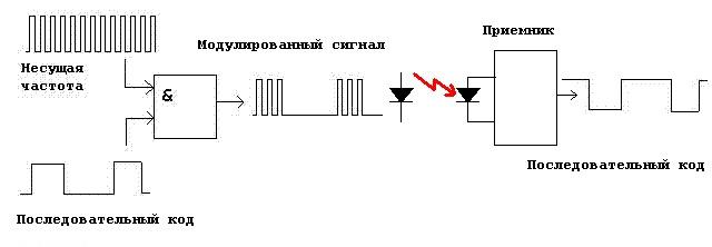
By modulating the signal at the transmitter input with a serial code, we receive a modulated signal at the transmitter output, which consists of a carrier (main) frequency and a serial code, in the form of bursts of pulses. A long pulse is one, a short pulse is zero. As a result, we can transmit and receive binary code.
Now let's move on to a small example of receiving IR signals using the LaunchPad MSP-EXP430G2 development board from Texas Instruments. We need to connect our IR receiver (I used TSOP 4836) to our development board.
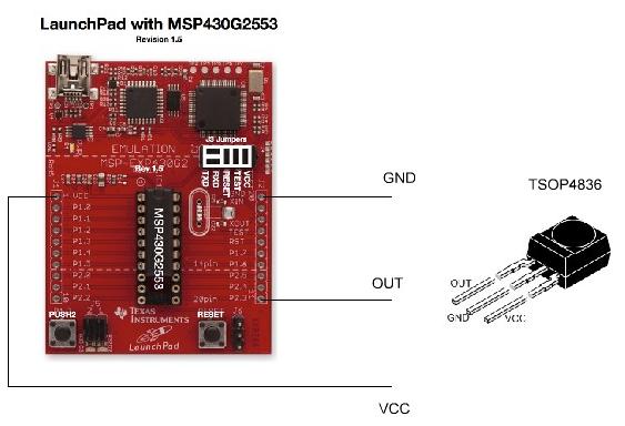
As we already said, the receiver chip TSOP has 3 OUT pins - IR receiver output pin. GND - common terminal (minus power supply). V CC — positive supply voltage output. As can be seen from the connection diagram, the receiver output is connected to pin No. 11.
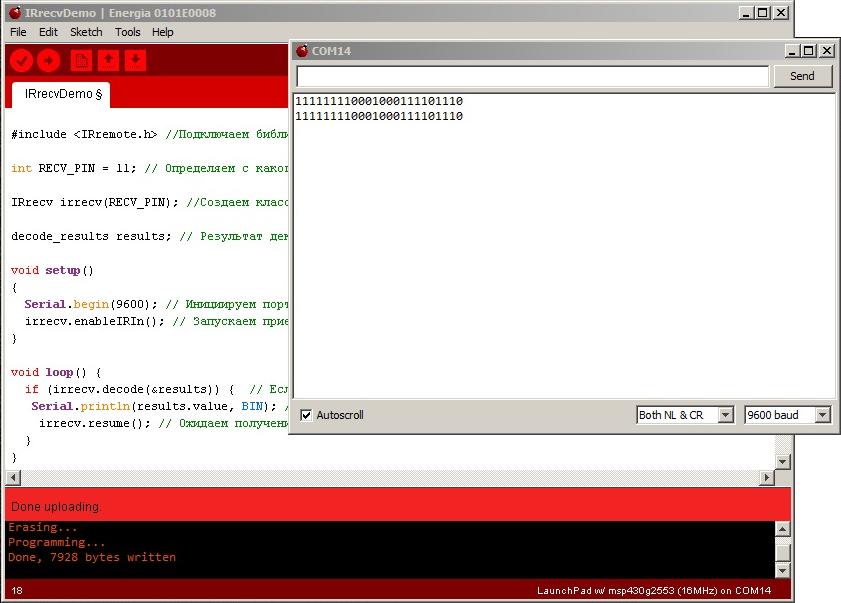
Let's start programming our LaunchPad. First, let's launch the LaunchPad - Energia programming environment.
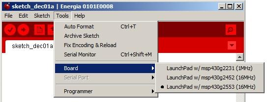
Select the type of controller used, compatible with LaunchPad msp430g2553. And let's start writing a simple sketch.
#include
//Connect the library to work with the IR receiver int RECV_PIN = 11; // Determine from which pin we will receive the signal from the TSOP4836 IR receiver
IRrecvirrecv(RECV_PIN); //Create an IR receiver class
decode_resultsresults; // Place the decoding result in a variable
Serial.begin(9600); // Initiate the port to monitor the results (Serial monitor)
irrecv.enableIRIn(); // Start receiving IR
if (irrecv.decode(&results)) ( // If any code is received from the IR receiver
Serial.println(results.value); // Display the numerical value of the pressed key on the IR remote control
irrecv.resume(); // Wait for the next variable to be received
Click the Upload button and flash our controller. Open SerialMonitor. Take the TV remote control or another IR remote control. We bring it to our TSOP 4836 receiver connected to the LaunchPad and start pressing the remote control buttons; the values of the remote control buttons in the decimal system will be displayed in the terminal. In order to get values in the binary system, you need to change the line by adding in what form you want to receive the data.
Serial.println(results.value, BIN ); // Display the numerical value of the pressed key on the IR remote control