Deflector with wind turbine hands. Wind turbine with vertical rotor made of plywood and tin
Properly designed ventilation system provides clean and Fresh air indoors. Its main condition efficient work is the presence of traction. Unfortunately, debris and dust entering the channels can disrupt the normal operation of the equipment. To prevent this from happening, a deflector must be installed on the ventilation pipe.
If there is no deflector on the ventilation pipe, then its diameter will gradually decrease. This is most facilitated by the fat that accumulates on the walls of the air duct. This is where dust and debris sticks.
The ventilation deflector is installed on the head of the pipe. At first glance, this protects the channels from debris that may enter from the outside. But it's not that simple. The device performs a number of functions, each of which is important.
Peculiarities
Installing a deflector on a ventilation pipe significantly increases draft. The device deflects air flows. As a result, a low pressure zone is formed at the exit from the ventilation shaft. Thanks to this, the air inside the pipe rises. This way the pressure is compensated.
There are many designs of deflectors, but they all work according to the principle described above. Interestingly, most modern devices have a narrowing of the channel. This allows for an increase in the speed at which air flows pass over the head of the pipe. As a result, the craving increases. This effect is called the “airbrush principle”.
If you use the deflector on the ventilation pipe correctly, you can achieve a significant increase in the efficiency of the entire system. At making the right choice device and its optimal installation, the power increase can reach 20 percent.
Attention! The ventilation deflector shows the highest efficiency when installed on ventilation ducts with bends and large horizontal sections.
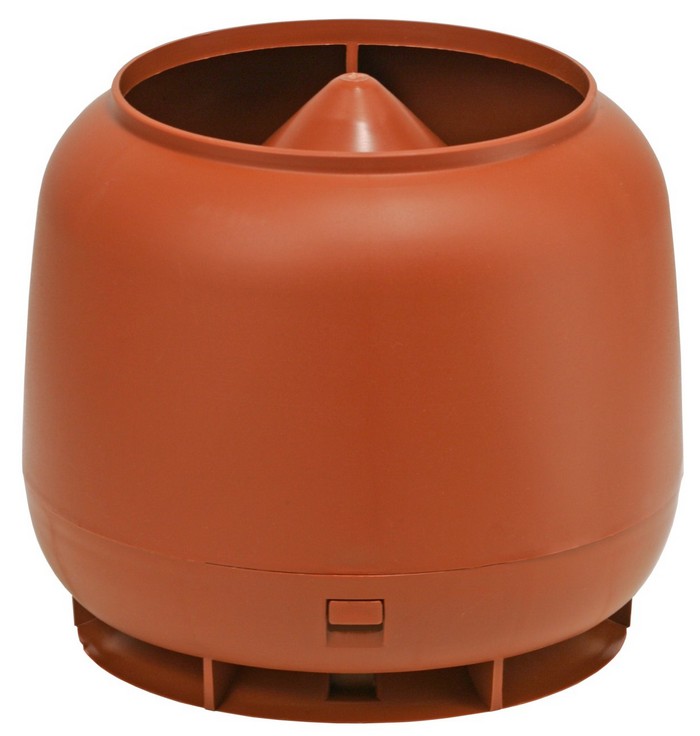
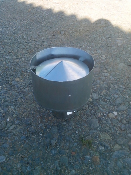
But the main purpose of the deflector is still to protect the air duct from the entry of debris, insects, small birds and precipitation. Since the device is installed externally, the case material is stainless steel or ceramic. In some cases, you can see regular plastic.
Advantages and disadvantages

Before assembling the unit with your own hands, you need to know not only its positive aspects, but also its negative ones. Let's focus on the positive first. The umbrella design effectively protects the pipe from precipitation and dirt, and an increase in traction can also be observed.
The main disadvantage of a deflector on a ventilation pipe is that when the wind blows from below, the flow hits the upper part of the structure and does not allow the air to exit normally. Therefore, problems with the operation of the system may sometimes occur. Fortunately, this happens quite rarely.
In addition, effective countermeasures were invented. Simply put, structures began to be equipped with two cones, which are connected by bases. Therefore, if you want to get a truly reliable unit, it is best to take this into account when creating a drawing.

Attention! The stronger the downward wind flow, the higher the pressure inside the ventilation deflector, which is installed on the pipe.
Kinds
There are many types of deflectors for ventilation pipes:
- The Tsaga deflector is very popular. The device has gained high popularity due to its simplicity of design and high efficiency.
- The Grigorovich deflector is very popular.
- The H-shaped apparatus is most effective when installed on chimneys.
It is also quite common to find open structures. Since there are quite a lot of various designs on the market, they are classified according to the following parameters:
- pommel shape,
- rotary or turbine operating principle,
- weather vane type.
The material from which the deflector is made plays a special role. Eg, plastic products They have a relatively low price, but their service life is not very long. You can also note the sophisticated appearance.

It is because of aesthetics that plastic deflectors can be seen on most pipes in private homes. Unfortunately, plastic cannot withstand high temperatures, so it cannot be installed on chimneys.
A rotating ventilation deflector enhances traction and effectively protects the channels from various debris getting inside. The main feature of the device is its spherical shape.
A rotary pipe vent may also be called a turbine vent. The device is capable of powering a turbine using wind energy. Inside, the air swirls like a tornado. This, in turn, increases draft in the duct. As a result, you can observe good traction even in summer.
Grigorovich deflector
There are many types of ventilation deflectors for pipes. If we take into account the design, which combines simplicity and efficiency, then this is, of course, Grigorovich’s unit.
This pipe ventilation deflector has a truncated cone. It is also called a diffuser. The ventilation pipe itself should fit slightly into it. A protective umbrella is mounted on top. A structure is installed underneath it to ensure reduced pressure even in crosswinds. It has the shape of a cone. Of course, similar design feature increases traction force.
Making a deflector with your own hands
Preparatory work

To make a ventilation deflector with your own hands and install it on a pipe, you first need to perform certain preparatory work. The device consists of the following main elements:
- inlet pipe,
- diffuser,
- cap
The best material to choose is stainless steel. Its high anti-corrosion properties will ensure a long service life of the deflector on the ventilation pipe.

Before you start assembling it yourself, you need to ensure that you have the necessary tools, which include:
- Bulgarian,
- drill,
- clamps,
- hammer,
- roulette,
- metal scissors,
- bolts and nuts,
- rivets.
You also need to think about finding suitable sheet metal for the unit. Particular attention should be paid to protective equipment. Do not start work without gloves and glasses.
The preparatory process also includes creating a drawing for the ventilation deflector with your own hands. It must be admitted that this is quite not an easy task. Of course, the design itself cannot be called super-complicated, however, in order to obtain a unit suitable for long-term use, everything needs to be carefully calculated.

It would be optimal to take a ready-made drawing, for example, one from this article. But you must keep in mind that your pipe dimensions may be completely different. Therefore, additional adjustments may need to be made as the project progresses. The best option would be to contact a design office, where they will make you a ready-made project that you can bring to life with your own hands.
Assembly

After you have prepared all the right tool and take care of personal protection, you can begin the process itself. First you need to transfer the contours from the drawing to metal. In this case, special attention is paid to the following elements:
- cap,
- diffuser,
- outer cylinder
- racks.
The final result in the form of a ready-to-use unit depends on how carefully you draw everything. Once the marks are made, you can start cutting. required forms Of course, for this you will need metal scissors.

To connect the cut out elements together, use a rivet gun. In this case, the racks will act as a kind of bridges between the two parts of the main structure.
Attention! The racks must be cut from the same metal as the two main parts of the unit.
After the unit is assembled, it can be installed at the head of the pipe. In this case, the structure itself is secured using clamps. At this point, the manufacturing and installation process can be considered complete.
Results
The ventilation deflector is important element in the ventilation system. It allows you to increase system performance by 20 percent while protecting internal channels from debris, dust and precipitation. Most often, units of this class are made from stainless steel sheets, but other options are possible.
To ensure good draft in the chimney, it is necessary to install a structure that can increase the rate of removal of combustion products from the smoke duct. Therefore, if you own a house or extension with stove heating or a ventilation shaft, then you need a turbo deflector. With its help, you can not only increase draft, but also protect the chimney from the penetration of carbon monoxide, debris or precipitation, and also prevent the occurrence of the reverse draft effect. The cost of such a device is quite high. However, you can save money by making a turbo deflector with your own hands, using available materials and tools.
Types of deflectors
There are several types of deflectors. They differ from each other in shape and number of parts. At the same time, you can choose the materials that are used to create them to your taste. It could be:
- Cink Steel
- Stainless steel
Their shape can be very diverse: from cylindrical to round. The upper part of the deflector structure may have an umbrella in the form of a cone or gable roof. The device can also be equipped with various decorative elements, for example, a weather vane.
Let's take a closer look at several varieties:
- TsAGI deflector
A structure whose parts are connected by flange or other means. This device is made from of stainless steel, less often - galvanized. Its feature is its cylindrical shape.
- Round volper
Its shape resembles the TsAGI deflector, but its main difference is top part. This device is most often installed on chimneys in small extensions, for example, in bathhouses.
- Grigorovich deflector
If the site is located in an area with low winds, then such a device will provide excellent traction for many years. Experts call it a modified version of the TsAGI deflector.
- Disc Astato
This type of device is distinguished by its simplicity and efficiency. This open-type deflector is made of galvanized or stainless steel, which improves traction efficiency in any wind direction.
- H-shaped deflector
Its design is particularly reliable, since the deflector is made of stainless steel, and all parts are connected using the flange method. It can be installed in areas with any wind direction.
- Weather vane deflector
This version of the device is the most popular and widespread. It has a rotating body on which a small weather vane is attached. The construction is made from stainless steel.
- Rotating deflector
This device allows for maximum protection of the channel from clogging with debris and precipitation. Rotation occurs in one direction only. It is worth noting that it is necessary to monitor its condition, since when there is icing, as well as in calm conditions, the deflector will not work. Therefore, many people install it on gas boilers. It is also used as a rotary turbine, which is necessary for ventilation of residential and office spaces.
In addition, there is a Khanzhonkov deflector. However, it is currently not used, since more modified models of devices can be found on the market.
Principle of operation
A classic deflector consists of several parts:
- cylinder
- diffuser
- an umbrella that protects the chimney from the penetration of debris and precipitation
- ring bumpers that are mounted at the bottom of the device and around it
The device is installed on the chimney, which allows it to create an obstruction to the air flow. Thus, the wind is broken into a huge number of small air flow, which have very low intensity. This is necessary so that the wind flow captures the smoke that comes out of the smoke channel, which allows for increased draft. In addition, the deflector prevents the shock gas coming out of the pipe from entering back.
As experts note, if the chimney is incorrectly positioned on site, the deflector cannot operate at full capacity, so before installation, be sure to check the correct installation of the duct.
Also, the deflector can serve as a ventilation turbine, which is installed in systems with natural ventilation. Next, we will tell you in detail how to make a ventilation deflector with your own hands.
DIY turbo deflector
If you want to save your money and make a turbo deflector yourself, then to start work you need to prepare all the necessary materials, tools and drawings of all parts.
Required Tools
- Sheet of steel. It can be stainless or galvanized. The thickness should be between 0.5 and 1 mm.
- Scissors for cutting metal.
- Riveter.
- Drill and drill bits for metal.
- Several sheets of cardboard.
Preparation of the drawing
Before you start manufacturing parts, you need to make a detailed drawing of the future deflector. If you want to make a device quickly, we recommend using ready-made drawings from the Internet. At the same time, be sure to check that all the parameters match the necessary ones and are suitable for your specific case.
If you want to make a drawing of the deflector yourself, you can use our tips and recommendations that will help you do it as correctly as possible.
| Landing diameter | Width | Height | Base height |
| 160 | 270 | 260 | 70 |
| 200 | 290 | 290 | 70 |
| 250 | 350 | 345 | 110 |
| 300 | 400 | 365 | 110 |
| 315 | 400 | 365 | 110 |
| 355 | 450 | 385 | 110 |
| 400 | 495 | 465 | 140 |
| 500 | 615 | 635 | 225 |
| 630 | 790 | 700 | 250 |
The basis of the drawing is the internal diameter of the chimney. After receiving its size, you need to select the height of the deflector, as well as the width of the diffuser.
If your dimensions do not match those indicated in the table, then you can calculate them yourself in accordance with the proportions:
- The height of the deflector should be from 1.6 to 1.7 internal diameter your chimney.
- The width of the diffuser should be from 1.2 to 1.3 times the internal diameter.
- The width of the deflector should be between 1.7 and 10 times the internal diameter of the channel.
After this you need to do it on whatman paper detail drawing future deflector in accordance with the characteristics that you calculated. The drawing can be done manually using a pencil or in Adobe Photoshop or Adobe Illustrator. The dimensions of all parts must be in actual size.
If you cannot prepare a drawing yourself, contact specialists who will take all measurements and short time will prepare the necessary drawing.
An example of the drawing you should get:
Instructions
After you have made a detailed drawing, you need to cut out each part from paper.
As soon as all the paper blanks are ready, they need to be secured on a sheet of stainless or galvanized steel. Trace each piece with a marker. You can also use special chalk for metal coatings for this.
Using metal shears, each piece is cut out. It is worth noting that on cuts the edges must be bent by about 5 mm. To do this, use pliers. After this, use a hammer to knock out the bends. This is necessary so that the edges of future parts become twice as thin.
Roll the blank of the future diffuser into a cylinder. Next, drill holes to secure the parts with bolts or rivets. Some recommend using semi-automatic welding, which will not allow metal sheets to be burned through.
Do the same with the outer cylinder, and roll the blank for the cap into a cone shape and connect the ends using a riveter.
Next, you need to cut 3-4 lines from the remains of the steel sheets, the width of which is about 6 cm and the length is 20 cm. Bend them on both sides with a margin of 6 cm. Drill several holes for the bolts at a distance of 5 cm from the edge. Secure them on the cap. After this, use rivets and connect them first to the outer cylinder, and then to the cap.
Installation
Once your diffuser is completely ready, it needs to be installed on the chimney. This can be done in two ways:
- Installation on the chimney itself.
- Installation on a pipe, which is then put on the chimney duct.
Users on the Internet note that the second method of installing a turbo deflector is safer due to the fact that all the most complex procedures can be completed in advance, and the finished structure can be quickly installed on the roof.
Therefore, we will tell you how to install it this way:
- First of all, you need to prepare the pipe itself. Its diameter should be slightly larger than the diameter of the chimney. At one end you need to retreat about 15 cm and mark the places for drilling. The same must be done on the bottom of the deflector.
- After this, drill holes in both parts and check if they match.
- Secure the pipe and deflector with bolts.
- Next, you can put the finished structure on the chimney and secure it firmly with a clamp so that there are no gaps left.
If you want extra protection, you can treat the joints with a high-temperature resistant sealant.
Making a Grigorovich deflector with your own hands
Materials
To manufacture the Grigorovich deflector, it is necessary to prepare the following materials:
- A sheet of galvanized or stainless steel, the thickness of which should reach up to 1 mm.
- Metal rivets or bolts.
- Paper or thick cardboard to create a drawing of the future product.
- Scissors for cutting metal.
- Drill and drill bits for metal.
- Riveter.
Stages of creation
First you need to prepare a drawing on a sheet of Whatman paper. As in the previous version, the internal diameter of the chimney is taken as the basis. Next, you need to calculate the following parameters in ratios:
- The height of the structure should be approximately 1.7 times the diameter.
- The width of the protective Santa should be 2 times the internal diameter of the chimney duct.
- The width of the diffuser should be approximately 1.3 times the diameter.
After this, you need to prepare a drawing, which should look something like this:
Bend approximately 5 mm from each edge to secure the parts. Beat each bend with a hammer, reducing its thickness by about 2 times. Drill 2-3 holes in them and connect the parts together so that the diffuser has the shape of a cylinder and the protective umbrella has the shape of a cone.
As in the previous instructions, make several strips and use them to connect the cap and the diffuser itself.
The most common problem in ventilation systems and chimneys is weak draft. Due to insufficient circulation, polluted air cannot be removed outside, and smoke from the boiler completely enters the room. A turbo deflector for ventilation of a private house and other buildings will help correct all these problems.
Device and how it works
The rotary turbine is used in systems with natural ventilation. Consists of an active deflector head with blades mounted on a base using zero-resistance bearings. Thanks to the latter, the turbine rotates at the same speed even in gusty wind conditions.
The principle of operation is as follows: the wind, hitting the blades, forces the head of the device to move, thereby discharging the air in the system and improving traction. In order for the turbine to start working, a wind speed of 0.5 m/s is sufficient, since all parts are made of thin and light material. The stronger the wind, the higher the power of the turbo deflector. Compared to conventional deflectors, the efficiency of this device is 2 times higher.
 Principle of operation
 Note! The head always rotates in only one direction, regardless of the direction of the wind, which is extremely important for systems connected to geysers. In the event of a strong gust of wind, the flame will not go out.
Rotary turbines are manufactured with three different types reasons:
- round;
- square;
- flat square.
Available with nozzle sizes from 10 to 68 cm.
Application area
The turbo deflector can be used not only for private houses and other residential premises, but also for industrial and agricultural ones. In livestock farms, turbines are installed to remove gases and moisture, and processing plants to save energy to reduce production costs. Rotary deflectors are also suitable for swimming pools, sports complexes and other public places.

Turbo deflectors with a base size from 11 to 19.5 cm are recommended to be installed for ventilation of cellars, garages and rooms. From 20 to 31.5 cm are used for rooms with an area of up to 50 m2, from 35 to 68 cm are used for apartment buildings and buildings with a large area, including livestock farms, warehouses and so on.
Advantages and disadvantages
Advantages of the turbo deflector compared to other similar devices:
- does not consume electricity - the rotary turbine works due to the power of the wind, so its operation does not require electric current;
- the possibility of precipitation getting into the ventilation or smoke exhaust system is eliminated, and due to the closed and movable upper part, debris or birds will not be able to get inside;
- turbine parts are made of high quality aluminum or stainless and galvanized steel;
- the moving head discharges the air more efficiently than fixed devices, preventing the room from overheating in hot weather, thereby reducing electricity costs for air conditioning;
- removes excess moisture, preventing condensation from forming on the walls and under the roof of the building, as well as accumulating in insulation and other materials, thereby extending their service life;
- the number of ice build-ups in ventilation ducts with a rotating turbine is noticeably less than that of stationary deflectors;
- all parts of the rotary turbo deflector are securely fastened, even with a strong gust of wind the device will not be torn off the pipe or distorted;
- has an aesthetic appearance, thanks to which it can also be used on residential buildings;
- ecologically safe device and simple maintenance;
- The service life of the turbo deflector is 15 years.
 Advantages of a turbo deflector
 The main disadvantage is that in the event of a complete absence of wind, the active head of the rotary turbine will stop moving. If it stops during a period of frost with precipitation, then there is a possibility of it freezing, which is why the device will not be able to start rotating again.
Rules for selection and installation with your own hands
To install a turbo deflector, you do not need to have any special skills or equipment. Thanks to its low weight and reliable design it can be easily installed by one person. The average installation time is no more than two hours. The device is installed at the highest point of the roof and along the ridge (at a distance of 4 to 6 m to the next deflector). If you place the turbine high, this will eliminate the possibility of snow getting inside the ventilation duct when sediment forms near it. Valves can be used in ductwork to control ventilation.
When installing a rotary turbine on chimney, it should be noted that the temperature in it should not exceed +100°C. For high temperature systems, high temperature nozzles must be used.
 Diagram of installing a deflector on part of the ventilation ducts with a transition
 Recommendation! There are a lot of manufacturers who claim that their products are the best. But before you buy a turbo deflector, you should carefully study the market and choose a device that has certificates of quality and safety tests, as well as a warranty period and a long service life.
You can make a turbo deflector with your own hands, but compared to simpler fixed models, this one will take more time, and you will need to cut out many identical petals. Accurate calculations and drawings are also important. Before you start cutting metal, it is recommended to make patterns from cardboard.
Price
The cost of a rotary turbine directly depends on the size of the connecting channel and the material from which it is made. Turbo deflectors made of galvanized steel are cheaper than models made of stainless steel. The average price of a galvanized rotary turbine TD-110 starts from 2200 rubles, and a stainless steel one from 3400 rubles.

The turbo deflector saves a significant amount of electricity and helps maintain a comfortable indoor temperature. The rotary turbine solves the problem of excessive dampness and musty air even in large multi-storey buildings, removes dust and fumes harmful substances. Thanks to the constant movement of the active head, the possibility of the rod tipping over is completely eliminated. Already in the first year of use, the turbo deflector pays for itself due to energy savings.
Russia occupies a dual position with regard to wind energy resources. On the one hand, thanks to the huge total area and due to the abundance of flat areas, there is generally a lot of wind, and it is mostly even. On the other hand, our winds are predominantly low-potential and slow, see Fig. On the third, in sparsely populated areas the winds are violent. Based on this, the task of installing a wind generator on the farm is quite relevant. But in order to decide whether to buy a fairly expensive device or make it yourself, you need to think carefully about which type (and there are a lot of them) to choose for what purpose.

Basic Concepts
- KIEV – wind energy utilization coefficient. When used to calculate a mechanistic model of flat wind (see below), it is equal to the efficiency of the rotor of a wind power plant (WPU).
- Efficiency – end-to-end efficiency of the APU, from the oncoming wind to the terminals of the electric generator, or to the amount of water pumped into the tank.
- Minimum working speed wind (MRS) - its speed at which the windmill begins to supply current to the load.
- The maximum permissible wind speed (MAS) is the speed at which energy production stops: the automation either turns off the generator, or puts the rotor in a weather vane, or folds it and hides it, or the rotor itself stops, or the APU is simply destroyed.
- Starting wind speed (SW) - at this speed, the rotor is able to turn without load, spin up and enter operating mode, after which the generator can be turned on.
- Negative starting speed (OSS) - this means that the APU (or wind turbine - wind power unit, or WEA, wind power unit) to start at any wind speed requires mandatory spin-up from an external energy source.
- Starting (initial) torque is the ability of a rotor, forcibly braked in the air flow, to create torque on the shaft.
- Wind turbine (WM) is part of the APU from the rotor to the shaft of the generator or pump, or other energy consumer.
- Rotary wind generator - an APU in which wind energy is converted into torque on the power take-off shaft by rotating the rotor in the air flow.
- The range of operating speeds of the rotor is the difference between MMF and MRS when operating at rated load.
- Low-speed windmill - in it the linear speed of the rotor parts in the flow does not significantly exceed the wind speed or is lower than it. The dynamic pressure of the flow is directly converted into blade thrust.
- High-speed windmill - the linear speed of the blades is significantly (up to 20 or more times) higher than the wind speed, and the rotor forms its own air circulation. The cycle of converting flow energy into thrust is complex.
Notes:
- Low-speed APUs, as a rule, have a KIEV lower than high-speed ones, but have a starting torque sufficient to spin up the generator without disconnecting the load and zero TAC, i.e. Absolutely self-starting and usable in the lightest winds.
- Slowness and speed are relative concepts. A household windmill at 300 rpm can be low-speed, but powerful APUs such as EuroWind, from which the fields of wind power plants and wind farms are assembled (see figure) and whose rotors make about 10 rpm, are high-speed, because with such a diameter, the linear speed of the blades and their aerodynamics over most of the span are quite “airplane-like”, see below.

What kind of generator do you need?
An electric generator for a domestic windmill must generate electricity over a wide range of rotation speeds and be able to self-start without automation or external power sources. In the case of using APU with OSS (spin-up wind turbines), which, as a rule, have high KIEV and efficiency, it must also be reversible, i.e. be able to work as an engine. At powers up to 5 kW this condition is satisfied electric cars with permanent magnets based on niobium (supermagnets); on steel or ferrite magnets you can count on no more than 0.5-0.7 kW.
Note: asynchronous alternating current generators or collector ones with a non-magnetized stator are completely unsuitable. When the wind force decreases, they will “go out” long before its speed drops to MPC, and then they will not start themselves.
The excellent “heart” of the APU with a power from 0.3 to 1-2 kW is obtained from an alternating current self-generator with a built-in rectifier; these are the majority now. First, they maintain an output voltage of 11.6-14.7 V over a fairly wide speed range without external electronic stabilizers. Secondly, the silicon valves open when the voltage on the winding reaches approximately 1.4 V, and before that the generator “does not see” the load. To do this, the generator needs to be spun up quite decently.
In most cases, a self-generator can be directly connected, without a gear or belt drive, to the shaft of a high-speed high-pressure engine, selecting the speed by selecting the number of blades, see below. “High-speed trains” have a low or zero starting torque, but the rotor, even without disconnecting the load, will have time to spin sufficiently before the valves open and the generator produces current.
Choosing according to the wind
Before deciding what kind of wind generator to make, let's decide on the local aerology. In gray-greenish(windless) areas of the wind map, only a sailing wind engine will be of any use(We’ll talk about them later). If you need a constant power supply, you will have to add a booster (rectifier with voltage stabilizer), charger, powerful battery, inverter 12/24/36/48 V DC to 220/380 V 50 Hz AC. Such a facility will cost no less than $20,000, and it is unlikely that it will be possible to remove long-term power of more than 3-4 kW. In general, with an unwavering commitment to alternative energy It's better to look for another source.
In yellow-green, low-wind places, if you need electricity up to 2-3 kW, you can use a low-speed vertical wind generator yourself. There are countless of them developed, and there are designs that are almost as good as “blade” ones in terms of KIEV and efficiency. industrial production.
If you plan to buy a wind turbine for your home, then it is better to focus on a wind turbine with a sail rotor. There are many controversies, and in theory everything is not yet clear, but they work. In the Russian Federation, “sailboats” are produced in Taganrog with a power of 1-100 kW.
In red, windy regions, the choice depends on the required power. In the range of 0.5-1.5 kW, homemade “verticals” are justified; 1.5-5 kW – purchased “sailboats”. “Vertical” can also be purchased, but will cost more than a horizontal APU. And finally, if you need a wind turbine with a power of 5 kW or more, then you need to choose between horizontal purchased “blades” or “sailboats”.
Note: Many manufacturers, especially the second tier, offer kits of parts from which you can assemble a wind generator with a power of up to 10 kW yourself. Such a kit will cost 20-50% less than a ready-made kit with installation. But before purchasing, you need to carefully study the aerology of the intended installation location, and then select the appropriate type and model according to the specifications.
About security
Parts of a wind turbine for domestic use in operation can have a linear speed exceeding 120 and even 150 m/s, and a piece of any hard material weighing 20 g, flying at a speed of 100 m/s, with a “successful” hit, it kills a healthy man outright. A steel or hard plastic plate 2 mm thick, moving at a speed of 20 m/s, cuts it in half.
In addition, most wind turbines with a power of more than 100 W are quite noisy. Many generate air pressure fluctuations of ultra-low (less than 16 Hz) frequencies - infrasounds. Infrasounds are inaudible, but are harmful to health and travel very far.
Note: in the late 80s there was a scandal in the United States - the largest wind farm in the country at that time had to be closed. Indians from a reservation 200 km from the field of its wind farm proved in court that their health disorders, which sharply increased after the wind farm was put into operation, were caused by its infrasounds.
Due to the above reasons, installation of APUs is allowed at a distance of at least 5 of their heights from the nearest residential buildings. In the courtyards of private households, it is possible to install industrially manufactured windmills that are appropriately certified. It is generally impossible to install APUs on roofs - during their operation, even low-power ones, alternating mechanical loads arise that can cause resonance of the building structure and its destruction.
Note: The height of the APU is considered to be the highest point of the swept disk (for bladed rotors) or geometric figure (for vertical APUs with a rotor on the shaft). If the APU mast or the rotor axis protrude even higher, the height is calculated by their top - the top.
Wind, aerodynamics, KIEV
A homemade wind generator obeys the same laws of nature as a factory one, calculated on a computer. And the homemaker needs to understand the basics of his work very well - most often he does not have at his disposal expensive, cutting-edge materials and technological equipment. The aerodynamics of the APU are oh so difficult...
Wind and KIEV
To calculate serial factory APUs, the so-called. flat mechanistic model of wind. It is based on the following assumptions:
- Wind speed and direction are constant within the effective rotor surface.
- Air is a continuous medium.
- The effective surface of the rotor is equal to the swept area.
- The energy of the air flow is purely kinetic.
Under such conditions, the maximum energy per unit volume of air is calculated using the school formula, assuming the air density under normal conditions is 1.29 kg*cubic. m. At a wind speed of 10 m/s, one cube of air carries 65 J, and from one square of the effective surface of the rotor, with 100% efficiency of the entire APU, 650 W can be removed. This is a very simplified approach - everyone knows that the wind is never perfectly even. But this has to be done to ensure repeatability of products - a common thing in technology.
The flat model should not be ignored, it gives a clear minimum of available wind energy. But air, firstly, is compressible, and secondly, it is very fluid (dynamic viscosity is only 17.2 μPa*s). This means that the flow can flow around the swept area, reducing the effective surface and KIEV, which is most often observed. But in principle, the opposite situation is also possible: the wind flows towards the rotor and the effective surface area will then be greater than the swept one, and the KIEV will be greater than 1 relative to it for a flat wind.
Let's give two examples. The first is a pleasure yacht, quite heavy; the yacht can sail not only against the wind, but also faster than it. Wind means external; the apparent wind must still be faster, otherwise how will it pull the ship?
The second is a classic of aviation history. During tests of the MIG-19, it turned out that the interceptor, which was a ton heavier than the front-line fighter, accelerates faster in speed. With the same engines in the same airframe.
The theorists did not know what to think, and seriously doubted the law of conservation of energy. In the end, it turned out that the problem was the cone of the radar radome protruding from the air intake. From its toe to the shell, an air compaction arose, as if raking it from the sides to the engine compressors. Since then, shock waves have become firmly established in theory as useful, and the fantastic flight performance of modern aircraft is due in no small part to their skillful use.
Aerodynamics
The development of aerodynamics is usually divided into two eras - before N. G. Zhukovsky and after. His report “On attached vortices” dated November 15, 1905 was the beginning new era in aviation.
Before Zhukovsky, they flew with flat sails: it was assumed that the particles of the oncoming flow gave all their momentum to the leading edge of the wing. This made it possible to immediately get rid of the vector quantity - angular momentum - which gave rise to tooth-breaking and most often non-analytical mathematics, move to much more convenient scalar purely energy relations, and ultimately obtain a calculated pressure field on the load-bearing plane, more or less similar to the real one.
This mechanistic approach made it possible to create devices that could, at the very least, take to the air and fly from one place to another, without necessarily crashing to the ground somewhere along the way. But the desire to increase speed, load capacity and other flight qualities increasingly revealed the imperfections of the original aerodynamic theory.
Zhukovsky's idea was this: the air travels a different path along the upper and lower surfaces of the wing. From the condition of continuity of the medium (vacuum bubbles by themselves do not form in the air) it follows that the velocities of the upper and lower flows descending from the trailing edge should be different. Due to the small, but finite viscosity of the air, a vortex should form there due to the difference in speeds.
The vortex rotates, and the law of conservation of momentum, just as immutable as the law of conservation of energy, is also valid for vector quantities, i.e. must also take into account the direction of movement. Therefore, right there, on the trailing edge, a counter-rotating vortex with the same torque should form. Due to what? Due to the energy generated by the engine.
For aviation practice, this meant a revolution: by choosing the appropriate wing profile, it was possible to send an attached vortex around the wing in the form of a circulation G, increasing its lift. That is, by spending part, and for high speeds and loads on the wing – most of the motor power, you can create an air flow around the device, allowing you to achieve better flight qualities.
This made aviation aviation, and not part of aeronautics: now the aircraft could create for itself the environment necessary for flight and no longer be a toy of air currents. All you need is a more powerful engine, and more and more powerful...
KIEV again
But the windmill does not have a motor. On the contrary, it must take energy from the wind and give it to consumers. And here it turns out - his legs were pulled out, his tail got stuck. We used too little wind energy for the rotor’s own circulation - it will be weak, the thrust of the blades will be low, and the KIEV and power will be low. We will give a lot to the circulation - the rotor will be on Idling spinning like crazy, but consumers again get little: they barely applied the load, the rotor slowed down, the wind blew away the circulation, and the rotor stopped.
The law of conservation of energy gives the “golden mean” right in the middle: we give 50% of the energy to the load, and for the remaining 50% we turn up the flow to the optimum. Practice confirms the assumptions: if the efficiency of a good pulling propeller is 75-80%, then the efficiency of a bladed rotor that is also carefully calculated and blown in a wind tunnel reaches 38-40%, i.e. up to half of what can be achieved with excess energy.
Modernity
Nowadays, aerodynamics, armed with modern mathematics and computers, is increasingly moving away from inevitably simplifying models towards an accurate description of the behavior of a real body in a real flow. And here, in addition to the general line - power, power, and once again power! – side paths are discovered, but promising precisely when the amount of energy entering the system is limited.
The famous alternative aviator Paul McCready created an airplane back in the 80s with two chainsaw motors with a power of 16 hp. showing 360 km/h. Moreover, its chassis was tricycle, non-retractable, and its wheels were without fairings. None of McCready's devices went online or went on combat duty, but two - one with piston engines and propellers, and the other a jet - for the first time in history flew around the globe without landing at the same gas station.

The development of the theory also affected the sails that gave birth to the original wing quite significantly. “Live” aerodynamics allowed the yachts to operate in winds of 8 knots. stand on hydrofoils (see figure); to accelerate such a hulk to required speed propeller, requires an engine of at least 100 hp. Racing catamarans sail at a speed of about 30 knots in the same wind. (55 km/h).
There are also finds that are completely non-trivial. Fans of the rarest and most extreme sport - base jumping - wearing a special wing suit, wingsuit, fly without a motor, maneuvering at a speed of more than 200 km/h (picture on the right), and then smoothly land in a pre-selected place. In which fairy tale do people fly on their own?

Many of the mysteries of nature were also resolved; in particular, the flight of a beetle. According to classical aerodynamics, it is not capable of flying. Just like the founder of the stealth aircraft, the F-117, with its diamond-shaped wing, is also unable to take off. And the MIG-29 and Su-27, which can fly tail first for some time, do not fit into any idea at all.
And why then, when working on wind turbines, not just fun and not a tool for destroying their own kind, but a source of a vital resource, do you need to dance away from the theory of weak flows with its flat wind model? Is there really no way to move forward?
What to expect from the classics?
However, one should not abandon the classics under any circumstances. It provides a foundation without which one cannot rise higher without relying on it. Just as set theory does not abolish the multiplication table, and quantum chromodynamics will not make apples fly up from the trees.
So, what can you expect with the classical approach? Let's look at the picture. On the left are types of rotors; they are depicted conditionally. 1 – vertical carousel, 2 – vertical orthogonal (wind turbine); 2-5 – bladed rotors with different numbers of blades with optimized profiles.

On the right along the horizontal axis is the relative speed of the rotor, i.e., the ratio of the linear speed of the blade to the wind speed. Vertical up - KIEV. And down - again, relative torque. A single (100%) torque is considered to be that which is created by a rotor forcibly braked in the flow with 100% KIEV, i.e. when all the flow energy is converted into rotating force.
This approach allows us to draw far-reaching conclusions. For example, the number of blades must be selected not only and not so much according to the desired rotation speed: 3- and 4-blades immediately lose a lot in terms of KIEV and torque compared to 2- and 6-blades that work well in approximately the same speed range. And the outwardly similar carousel and orthogonal have fundamentally different properties.
In general, preference should be given to bladed rotors, except in cases where extreme low cost, simplicity, maintenance-free self-starting without automation are required, and lifting onto a mast is impossible.
Note: Let's talk about sailing rotors in particular - they don't seem to fit into the classics.
Verticals
APUs with a vertical axis of rotation have an undeniable advantage for everyday life: their components requiring maintenance are concentrated at the bottom and no lifting is required. There remains, and even then not always, a thrust-support self-aligning bearing, but it is strong and durable. Therefore, when designing a simple wind generator, the selection of options should begin with verticals. Their main types are presented in Fig.

Sun
In the first position is the simplest one, most often called the Savonius rotor. In fact, it was invented in 1924 in the USSR by J. A. and A. A. Voronin, and the Finnish industrialist Sigurd Savonius shamelessly appropriated the invention, ignoring the Soviet copyright certificate, and began serial production. But the introduction of an invention in the future means a lot, so in order not to stir up the past and not disturb the ashes of the deceased, we will call this windmill a Voronin-Savonius rotor, or for short, VS.
The aircraft is good for the home-made man, except for the “locomotive” KIEV at 10-18%. However, in the USSR they worked a lot on it, and there are developments. Below we will look at an improved design, not much more complex, but according to KIEV, it gives bladers a head start.
Note: the two-blade aircraft does not spin, but jerks jerkily; The 4-blade is only slightly smoother, but loses a lot in KIEV. To improve, 4-troughs are most often divided into two floors - a pair of blades below, and another pair, rotated 90 degrees horizontally, above them. KIEV is preserved, and the lateral loads on the mechanics weaken, but the bending loads increase somewhat, and with a wind of more than 25 m/s such an APU is on the shaft, i.e. without a bearing stretched by cables above the rotor, it “tears down the tower.”
Daria
Next is the Daria rotor; KIEV – up to 20%. It is even simpler: the blades are made of a simple elastic tape without any profile. The theory of the Darrieus rotor is not yet sufficiently developed. It is only clear that it begins to unwind due to the difference in the aerodynamic resistance of the hump and the tape pocket, and then it becomes sort of high-speed, forming its own circulation.
The torque is small, and in the starting positions of the rotor parallel and perpendicular to the wind it is completely absent, so self-spin is possible only with an odd number of blades (wings?) In any case, the load from the generator must be disconnected during spin-up.
The Daria rotor has two more bad qualities. Firstly, when rotating, the thrust vector of the blade describes a full rotation relative to its aerodynamic focus, and not smoothly, but jerkily. Therefore, the Darrieus rotor quickly breaks down its mechanics even in a steady wind.
Secondly, Daria not only makes noise, but screams and squeals, to the point that the tape breaks. This happens due to its vibration. And the more blades, the stronger the roar. So, if they make Daria, they have two blades, from expensive, high-strength sound-absorbing materials (carbon, mylar), and a small aircraft is used for spinning in the middle of the mast-pole.
Orthogonal
At pos. 3 – orthogonal vertical rotor with profiled blades. Orthogonal because the wings stick out vertically. The transition from BC to orthogonal is illustrated in Fig. left.

The angle of installation of the blades relative to the tangent to the circle touching the aerodynamic foci of the wings can be either positive (in the figure) or negative, depending on the wind force. Sometimes the blades are made rotating and weather vanes are placed on them, automatically holding the “alpha”, but such structures often break.
The central body (blue in the figure) allows you to increase the KIEV to almost 50%. In a three-bladed orthogonal, it should have the shape of a triangle in cross-section with slightly convex sides and rounded corners, and with a larger number of blades a simple cylinder is sufficient. But the theory for the orthogonal gives an unambiguous optimal number of blades: there should be exactly 3 of them.
Orthogonal refers to high-speed wind turbines with OSS, i.e. necessarily requires promotion during commissioning and after calm. According to the orthogonal scheme, serial maintenance-free APUs with a power of up to 20 kW are produced.
Helicoid
Helicoidal rotor, or Gorlov rotor (item 4) is a type of orthogonal that ensures uniform rotation; an orthogonal with straight wings “tears” only slightly weaker than a two-bladed aircraft. Bending the blades along a helicoid allows one to avoid losses of CIEV due to their curvature. Although the curved blade rejects part of the flow without using it, it also scoops part into the zone of highest linear speed, compensating for losses. Helicoids are used less often than other wind turbines, because Due to the complexity of manufacturing, they are more expensive than their counterparts of equal quality.
Barrel raking
For 5 pos. – BC type rotor surrounded by a guide vane; its diagram is shown in Fig. on right. It is rarely found in industrial applications, because expensive land acquisition does not compensate for the increase in capacity, and the material consumption and complexity of production are high. But a do-it-yourselfer who is afraid of work is no longer a master, but a consumer, and if you need no more than 0.5-1.5 kW, then for him a “barrel-raking” is a tidbit:

- A rotor of this type is absolutely safe, silent, does not create vibrations and can be installed anywhere, even on a playground.
- Bending a galvanized “trough” and welding a frame of pipes is nonsense work.
- The rotation is absolutely uniform, the mechanical parts can be taken from the cheapest or from the trash.
- Not afraid of hurricanes - too much strong wind cannot push into the “barrel”; a streamlined vortex cocoon appears around it (we will encounter this effect later).
- And the most important thing is that since the surface of the “barrel” is several times larger than that of the rotor inside, the KIEV can be over-unity, and the rotational moment already at 3 m/s for a “barrel” of three-meter diameter is such that a 1 kW generator with a maximum load of They say it’s better not to twitch.
Video: Lenz wind generator
In the 60s in the USSR, E. S. Biryukov patented a carousel APU with a KIEV of 46%. A little later, V. Blinov achieved 58% KIEV from a design based on the same principle, but there is no data on its tests. And full-scale tests of Biryukov’s APU were carried out by employees of the magazine “Inventor and Innovator”. A two-story rotor with a diameter of 0.75 m and a height of 2 m in a fresh wind spun a 1.2 kW asynchronous generator to full power and withstood 30 m/s without breakdown. Drawings of Biryukov's APU are shown in Fig.

- rotor made of galvanized roofing;
- self-aligning double row ball bearing;
- shrouds – 5 mm steel cable;
- axis-shaft – steel pipe with a wall thickness of 1.5-2.5 mm;
- aerodynamic speed control levers;
- speed control blades – 3-4 mm plywood or sheet plastic;
- speed control rods;
- speed controller load, its weight determines the rotation speed;
- drive pulley - a bicycle wheel without a tire with a tube;
- thrust bearing - thrust bearing;
- driven pulley – standard generator pulley;
- generator.
Biryukov received several copyright certificates for his APU. First, pay attention to the cut of the rotor. When accelerating, it works like an aircraft, creating a large starting torque. As it spins, a vortex cushion is created in the outer pockets of the blades. From the wind's point of view, the blades become profiled and the rotor becomes a high-speed orthogonal, with the virtual profile changing according to the wind strength.
Secondly, the profiled channel between the blades acts as a central body in the operating speed range. If the wind intensifies, then a vortex cushion is also created in it, extending beyond the rotor. The same vortex cocoon appears as around the APU with a guide vane. The energy for its creation is taken from the wind, and it is no longer enough to break the windmill.
Thirdly, the speed controller is intended primarily for the turbine. It keeps its speed optimal from the KIEV point of view. And the optimum generator rotation speed is ensured by the choice of mechanical transmission ratio.
Note: after publications in the IR for 1965, the Armed Forces of Ukraine Biryukova sank into oblivion. The author never received a response from the authorities. The fate of many Soviet inventions. They say that some Japanese became a billionaire by regularly reading Soviet popular-technical magazines and patenting everything worthy of attention.
Lopastniki
As stated, according to the classics, a horizontal wind generator with a bladed rotor is the best. But, firstly, it needs a stable wind of at least medium strength. Secondly, the design for a do-it-yourselfer is fraught with many pitfalls, which is why often the fruit of long hard work, at best, illuminates a toilet, hallway or porch, or even turns out to only be able to unwind itself.

According to the diagrams in Fig. Let's take a closer look; positions:
- Fig. A:
- rotor blades;
- generator;
- generator frame;
- protective weather vane (hurricane shovel);
- current collector;
- chassis;
- swivel unit;
- working weather vane;
- mast;
- clamp for the shrouds.
- Fig. B, top view:
- protective weather vane;
- working weather vane;
- protective weather vane spring tension regulator.
- Fig. G, current collector:
- collector with copper continuous ring busbars;
- spring-loaded copper-graphite brushes.
Note: Hurricane protection for a horizontal blade with a diameter of more than 1 m is absolutely necessary, because he is not capable of creating a vortex cocoon around himself. With smaller sizes, it is possible to achieve a rotor endurance of up to 30 m/s with propylene blades.
So, where do we stumble?
Blades

Expecting to achieve a power on the generator shaft of more than 150-200 W on blades of any size cut from a thick-walled plastic pipe, as is often advised, is the hope of a hopeless amateur. A pipe blade (unless it is so thick that it is simply used as a blank) will have a segmented profile, i.e. its top or both surfaces will be arcs of a circle.
Segmented profiles are suitable for incompressible media, such as hydrofoils or propeller blades. For gases, a blade of variable profile and pitch is needed, for an example, see Fig.; span - 2 m. This will be a complex and labor-intensive product, requiring painstaking calculations based on theory, pipe blowing and full-scale testing.
Generator
If the rotor is mounted directly on its shaft, the standard bearing will soon break - there is no equal load on all the blades in windmills. You need an intermediate shaft with a special support bearing and a mechanical transmission from it to the generator. For large windmills, the support bearing is a self-aligning double-row one; V best models– three-tiered, Fig. D in Fig. higher. This allows the rotor shaft not only to bend slightly, but also to move slightly from side to side or up and down.
Note: It took about 30 years to develop a support bearing for the EuroWind type APU.
Emergency weather vane
The principle of its operation is shown in Fig. B. The wind, intensifying, puts pressure on the shovel, the spring stretches, the rotor warps, its speed drops and eventually it becomes parallel to the flow. Everything seems to be fine, but it was smooth on paper...
On a windy day, try holding a boiler lid or a large saucepan by the handle parallel to the wind. Just be careful - the fidgety piece of iron can hit you in the face so hard that it breaks your nose, cuts your lip, or even knocks out your eye.
Flat wind occurs only in theoretical calculations and, with sufficient accuracy for practice, in wind tunnels. In reality, a hurricane damages windmills with a hurricane shovel more than completely defenseless ones. It’s better to change damaged blades than to do everything again. In industrial installations it is a different matter. There, the pitch of the blades, each individually, is monitored and adjusted by automation under the control of the on-board computer. And they are made from heavy-duty composites, not water pipes.
Current collector
This is a regularly serviced unit. Any power engineer knows that the commutator with brushes needs to be cleaned, lubricated, and adjusted. And the mast is made from a water pipe. If you can’t climb, once every month or two you’ll have to throw the entire windmill down to the ground and then pick it up again. How long will he last from such “prevention”?
Video: bladed wind generator + solar panel for power supply to a dacha
Mini and micro
But as the size of the paddle decreases, the difficulties fall according to the square of the wheel diameter. It is already possible to manufacture a horizontal bladed APU on your own with a power of up to 100 W. A 6-bladed one would be optimal. With more blades, the diameter of the rotor designed for the same power will be smaller, but they will be difficult to firmly attach to the hub. Rotors with less than 6 blades need not be taken into account: a 2-blade 100 W rotor needs a rotor with a diameter of 6.34 m, and a 4-blade of the same power needs 4.5 m. For a 6-blade, the power-diameter relationship is expressed as follows :
- 10 W – 1.16 m.
- 20 W – 1.64 m.
- 30 W – 2 m.
- 40 W – 2.32 m.
- 50 W – 2.6 m.
- 60 W – 2.84 m.
- 70 W – 3.08 m.
- 80 W – 3.28 m.
- 90 W – 3.48 m.
- 100 W – 3.68 m.
- 300 W – 6.34 m.
It would be optimal to count on a power of 10-20 W. Firstly, a plastic blade with a span of more than 0.8 m will not withstand winds of more than 20 m/s without additional protection measures. Secondly, with a blade span of up to the same 0.8 m, the linear speed of its ends will not exceed the wind speed by more than three times, and the requirements for profiling with twist are reduced by orders of magnitude; here a “trough” with a segmented pipe profile, pos. B in Fig. And 10-20 W will provide power to a tablet, recharge a smartphone, or light up a house-saving light bulb.

Next, select a generator. A Chinese motor is perfect - wheel hub for electric bicycles, pos. 1 in Fig. Its power as a motor is 200-300 W, but in generator mode it will give up to about 100 W. But will it suit us in terms of speed?
The speed index z for 6 blades is 3. The formula for calculating the rotation speed under load is N = v/l*z*60, where N is the rotation speed, 1/min, v is the wind speed, and l is the rotor circumference. With a blade span of 0.8 m and a wind of 5 m/s, we get 72 rpm; at 20 m/s – 288 rpm. A bicycle wheel also rotates at approximately the same speed, so we will take off our 10-20 W from a generator capable of producing 100. You can place the rotor directly on its shaft.
But here the following problem arises: after spending a lot of work and money, at least on a motor, we got... a toy! What is 10-20, well, 50 W? But you can’t make a bladed windmill capable of powering even a TV at home. Is it possible to buy a ready-made mini-wind generator, and wouldn’t it be cheaper? As much as possible, and as cheaply as possible, see pos. 4 and 5. In addition, it will also be mobile. Place it on a stump and use it.
The second option is if it’s lying around somewhere stepper motor from an old 5- or 8-inch floppy drive, or from the paper drive or carriage of an unusable inkjet or dot matrix printer. It can work as a generator, and attaching a carousel rotor from cans to it (pos. 6) is easier than assembling a structure like the one shown in pos. 3.
In general, the conclusion regarding “blade blades” is clear: homemade ones are more likely for tinkering to your heart’s content, but not for real long-term energy output.
Video: the simplest wind generator for lighting a dacha
Sailboats

The sailing wind generator has been known for a long time, but soft panels on its blades (see figure) began to be made with the advent of high-strength, wear-resistant synthetic fabrics and films. Multi-bladed windmills with rigid sails have spread widely around the world as a drive for low-power automatic water pumps, but their technical specifications are lower even than those of carousels.
However, a soft sail like a windmill wing, it seems, turned out to be not so simple. The point is not about wind resistance (manufacturers do not limit the maximum permissible wind speed): sailboat sailors already know that it is almost impossible for the wind to tear the panel of a Bermuda sail. Most likely, the sheet will be torn out, or the mast will be broken, or the whole vessel will make an “overkill turn.” It's about energy.
Unfortunately, exact test data cannot be found. Based on user reviews, it was possible to create “synthetic” dependencies for the installation of a Taganrog-made wind turbine-4.380/220.50 with a wind wheel diameter of 5 m, a wind head weight of 160 kg and a rotation speed of up to 40 1/min; they are presented in Fig.

Of course, there can be no guarantees for 100% reliability, but it is clear that there is no smell of a flat-mechanistic model here. There is no way a 5-meter wheel in a flat wind of 3 m/s can produce about 1 kW, at 7 m/s reach a plateau in power and then maintain it until a severe storm. Manufacturers, by the way, claim that the nominal 4 kW can be obtained at 3 m/s, but when installed by forces based on the results of studies of local aerology.
There is also no quantitative theory to be found; The developers' explanations are unclear. However, since people buy Taganrog wind turbines and they work, we can only assume that the declared conical circulation and propulsive effect are not a fiction. In any case, they are possible.
Then, it turns out, IN FRONT of the rotor, according to the law of conservation of momentum, a conical vortex should also arise, but expanding and slow. And such a funnel will drive the wind towards the rotor, it effective surface it will turn out to be more swept, and KIEV will be over-unit.
Field measurements of the pressure field in front of the rotor, even with a household aneroid, could shed light on this issue. If it turns out to be higher than on the sides, then, indeed, the sailing APUs work like a beetle flies.
Homemade generator
From what has been said above, it is clear that it is better for home-made people to take on either verticals or sailboats. But both are very slow, and transmission to a high-speed generator is extra work, extra costs and losses. Is it possible to make an efficient low-speed electric generator yourself?
Yes, you can, on magnets made of niobium alloy, so-called. supermagnets. The manufacturing process of the main parts is shown in Fig. Coils - each of 55 turns of 1 mm copper wire in heat-resistant high-strength enamel insulation, PEMM, PETV, etc. The height of the windings is 9 mm.

Pay attention to the grooves for the keys in the rotor halves. They must be positioned so that the magnets (they are glued to the magnetic core with epoxy or acrylic) converge with opposite poles after assembly. “Pancakes” (magnetic cores) must be made of a soft magnetic ferromagnet; Regular structural steel will do. The thickness of the “pancakes” is at least 6 mm.
In general, it is better to buy magnets with an axial hole and tighten them with screws; supermagnets attract with terrible force. For the same reason, a cylindrical spacer 12 mm high is placed on the shaft between the “pancakes”.
The windings that make up the stator sections are connected according to the diagrams also shown in Fig. The soldered ends should not be stretched, but should form loops, otherwise the epoxy with which the stator will be filled may harden and break the wires.
The stator is poured into the mold to a thickness of 10 mm. There is no need to center or balance, the stator does not rotate. The gap between the rotor and stator is 1 mm on each side. The stator in the generator housing must be securely secured not only from displacement along the axis, but also from rotation; a strong magnetic field with current in the load will pull it along with it.
Video: DIY windmill generator
Conclusion
And what do we have in the end? The interest in “blade blades” is explained rather by their spectacular appearance than real performance qualities in a homemade version and at low power. A homemade carousel APU will provide “standby” power for charging a car battery or powering a small house.
But with sailing APUs it is worth experimenting with craftsmen with a creative streak, especially in the mini version, with a wheel 1-2 m in diameter. If the developers’ assumptions are correct, then it will be possible to remove all 200-300 W from this one, using the Chinese engine-generator described above.
Andrey said:
Thank you for your free consultation... And the prices “from companies” are not really expensive, and I think that craftsmen from the outback will be able to make generators similar to yours. And Li-po batteries can be ordered from China, inverters in Chelyabinsk make very good ones (with smooth sine). And sails, blades or rotors are another reason for the flight of thought of our handy Russian men.
Ivan said:
question:
For windmills with a vertical axis (position 1) and the “Lenz” option, it is possible to add an additional part - an impeller that points in the direction of the wind, and covers the useless side from it (going towards the wind). That is, the wind will not slow down the blade, but this “screen”. Positioning downwind with the “tail” located behind the windmill itself below and above the blades (ridges). I read the article and an idea was born.
By clicking the “Add comment” button, I agree with the site.
Excessive humidity and odors create an unhealthy atmosphere and even cause diseases. The quality of ventilation in a home, office or workplace directly affects the level of comfort, do you agree with this?
That's why it's smart arranged ventilation is the most important condition when putting construction projects into operation. A turbo deflector for ventilation helps to establish high-quality air exchange. But which one to choose and install correctly so as not to call specialists?
We will try to answer all questions in detail - this material discusses the operating principle, existing types of turbo deflectors, and installation features. Attention is also paid to maintenance and repair issues.
For a better understanding of the information presented, visual photographs and diagrams of the design of rotary deflectors have been selected, and video recommendations for troubleshooting breakdowns have been provided. The information is structured and even an inexperienced home craftsman will find it easy to understand the intricacies of choosing, installing and repairing a rotary deflector.
The operation of the turbo deflector is based on following principles: using wind energy, the device creates a vacuum in the ventilation shaft, increases draft and draws polluted air from the room, ventilation duct, and under-roof space.
No matter how the direction and strength of the wind changes, the rotating head (impeller) always rotates in one direction and creates a partial vacuum in the ventilation shaft.
Image gallery
Turbine installation rules
Ventilation turbines can be installed directly on a pitched or straight roof, at the outlet of a chimney or ventilation shaft. The placement location depends on the application of the turbine.