My homemade wind generator using a stepper motor. How to assemble a wind generator from three hard drives and one pump from a washing machine Generator from magnets from a hard drive
You will definitely like this material, as in it we will look at a way to obtain a simple generator from an old computer CD/DVD drive.
First of all, we suggest you familiarize yourself with the author’s video
Let's look at what we need:
- old CD/DVD drive;
- wire cutters;
- soldering iron;
- any plastic case;
- wires;
- hexagon;
- washer.
According to the author homemade generator, the idea is quite effective, since the ratio of the gear ratio to the motor that drives the gear that extends the disc tray is quite large. Thus, it is possible that at low revolutions of the same gear, good revolutions will be obtained on the electric motor, and we will be able to obtain a generator. We will find out at the end of the review whether our plans will work out or not, but now let’s get to work.
First you need to unsolder the board on which the motor is mounted.

Next, we cut off the part of the plastic drive housing that holds the motor, as well as the gear we need. Later we will derive a handle from this gear so that we can turn it and generate electricity.


We take the first wire and solder it to one of the motor contacts.

Solder the second wire to the second contact.

To test the generator, the author of the idea uses UBS inputs, which are installed in a plastic case. Therefore, he glues a piece of the drive with a motor and gear into this body using a glue gun.

To make a handle you will need a hexagon and a washer. These parts need to be attached to each other. The author does this by soldering.

Solder the wires to the pins of the USB connectors.

On the second half of the plastic case you need to make a hole for the gear protrusion.

Finally glue it homemade pen to the gear lug. Our generator is ready.
There is a way to get electricity absolutely free. It is enough to make and install a wind generator on your site. Today, this cannot replace traditional sources of electricity, but it will add a few pleasant percentages of proud independence to the household. The most important thing is that you can “concoct” a full-fledged generator from literally any old trash and garbage.
We will need
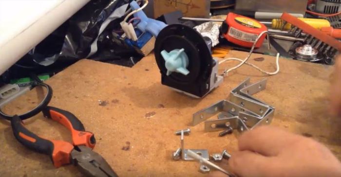
First of all, you need to get a pump from an automatic washing machine. It is used to pump water from the drum into the sewer and is located at the very bottom. You will also need four faulty hard drives, a long pole to install the structure, numerous bolts, nuts, and washers. Finally, we need wires.
What is a pump for?

The pump will be used as the same generator that will generate electricity. The pump consists of a movable rotor with permanent magnets and a movable stator with a U-shaped magnetic core, as well as a coil that is attached to this structure. The rotor can be easily pulled out. Thanks to the mentioned permanent magnets, such a pump makes an excellent generator, capable of producing voltage up to 250 V.
Generator manufacturing process
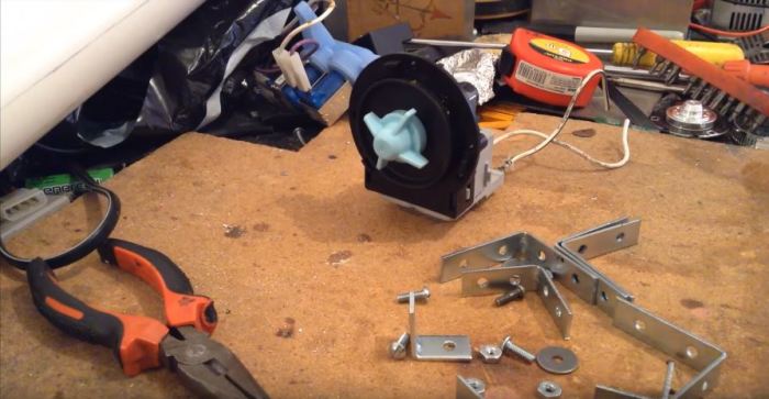
It is best to secure the pump using a clamp, which is most easily made from steel corners. They will likely need to be trimmed accordingly. You can safely make an additional hole in the magnetic core of the pump for more reliable fixation. That's basically all that needs to be done at this stage.
The manufacturing process of blades and their fastening

Blades for a wind generator can be made from PVC pipes. To do this, cut it into three equal parts lengthwise. From such blanks you can then make more “elegant” elements. In the places where the blades are attached, do not forget to make suitable holes for subsequent fastening. It is also necessary to make a tail blade from a similar material, which will guide the generator.

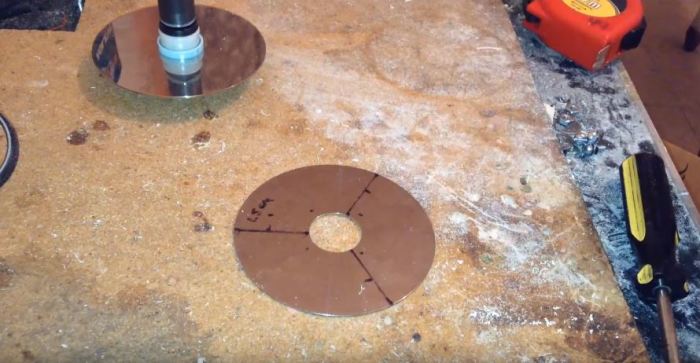
We will fix the blades on two disks from the HDD. The whole difficulty of this stage of work is to make holes in the disks in suitable places, and then screw the blades to them using prepared bolts and washers.
Swivel unit
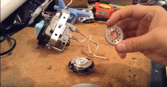
Small but very important detail. To produce a turning angle, you can use a motor from hard drive. It has very good bearings, and therefore this element will ideally cope with the task. It is on this element that the disk with the generator will be mounted.
General assembly

Now all that remains is to collect wind generator, attach the wires to our pole, install a rotating element on it, and also lift and place the “mill” in suitable place. After completion of the work, it is good to carry out small tests. Of course, the wind generator will not provide a maximum of 250 V, but the result of the work will still be pleasant! Detailed Process the assembly can be seen in the video below.
I want even more interesting and useful tips For summer cottage for next season? How about we find out and turn it into something useful for the household.
Biking past summer cottages, I saw a working wind generator:
The large blades rotated slowly but surely, the weather vane oriented the device in the direction of the wind.
I wanted to implement a similar design, although not capable of generating power sufficient to supply “serious” consumers, but still working and, for example, charging batteries or powering LEDs.
Stepper motors
One of the most effective options a small homemade wind generator is the use stepper motor(SD) (English) stepping (stepper, step) motor) - in such a motor, the rotation of the shaft consists of small steps. The windings of the stepper motor are combined into phases. When current is supplied to one of the phases, the shaft moves one step.
These engines are low speed and a generator with such an engine can be connected to wind turbine, Stirling engine or other low speed power source. When using a conventional (commutator) engine as a generator direct current to achieve the same results would require 10-15 times higher rotation speed.
A feature of the stepper is a fairly high starting moment (even without an electrical load connected to the generator), reaching 40 grams of force per centimeter.
Coefficient useful action generator with stepper motor reaches 40%.
To check the operation of the stepper motor, you can connect, for example, a red LED. By rotating the motor shaft, you can observe the glow of the LED. The polarity of the LED connection does not matter since the motor produces alternating current.
Five-inch floppy drives, as well as old printers and scanners, are a treasure trove of such fairly powerful engines.
Engine 1
For example, I have a SD from an old 5.25″ floppy drive that was still part of ZX Spectrum- a compatible computer "Byte".
Such a drive contains two windings, from the ends and the middle of which conclusions are made - a total of six wires: 
first winding coil 1) - blue (English) blue) and yellow (eng. yellow);
second winding coil 2) - red (English) red) and white (English) white);
brown brown) wires - leads from the midpoints of each winding (eng. center taps).

disassembled stepper motor
On the left you can see the rotor of the engine, on which the “striped” magnetic poles are visible - north and south. To the right you can see the stator winding, consisting of eight coils.
The resistance of half the winding is ~70 ohms.
I used this motor in the original design of my wind turbine.
Engine 2
A less powerful stepper motor at my disposal T1319635 companies Epoch Electronics Corp. from the scanner HP Scanjet 2400 It has five outputs (unipolar motor): 
first winding coil 1) - orange (English) orange) and black (English) black);
second winding coil 2) - brown (English) brown) and yellow (eng. yellow);
red (English) red) wire - terminals connected together from the midpoint of each winding (eng. center taps).
The resistance of half the winding is 58 ohms, which is indicated on the motor housing.
Engine 3
In an improved version of the wind generator, I used a stepper motor Robotron SPA 42/100-558, produced in the GDR and designed for 12 V: 
Wind turbine
There are two possible options for the location of the axis of the impeller (turbine) of a wind generator - horizontal and vertical.
Advantage horizontal(most popular) location axis located in the direction of the wind is more efficient use wind energy, the disadvantage is the complexity of the design.
I chose vertical arrangement axes - VAWT (vertical axis wind turbine), which significantly simplifies the design and does not require orientation downwind . This option is more suitable for mounting on the roof; it is much more effective in conditions of rapid and frequent changes in wind direction.
I used a type of wind turbine called a Savonius wind turbine. Savonius wind turbine). It was invented in 1922 Sigurd Johannes Savonius) from Finland. 
Sigurd Johannes Savonius
The operation of the Savonius wind turbine is based on the fact that resistance drag) the oncoming air flow - the wind of the concave surface of the cylinder (blade) is greater than the convex one.
Aerodynamic drag coefficients ( English drag coefficients) $C_D$
two-dimensional bodies:
concave half of the cylinder (1) - 2.30
convex half of the cylinder (2) - 1.20
flat square plate - 1.17
3D bodies:
concave hollow hemisphere (3) - 1.42
convex hollow hemisphere (4) - 0.38
sphere - 0.5
The indicated values are given for Reynolds numbers. Reynolds numbers) in the range $10^4 - 10^6$. The Reynolds number characterizes the behavior of a body in a medium.
Body resistance force to air flow $(F_D) = ((1 \over 2) (C_D) S \rho (v^2) ) $, where $\rho$ is air density, $v$ is speed air flow, $S$ is the cross-sectional area of the body.
Such a wind turbine rotates in the same direction, regardless of the wind direction: 
A similar operating principle is used in the cup anemometer. cup anemometer)- a device for measuring wind speed: 
Such an anemometer was invented in 1846 by Irish astronomer John Thomas Romney Robinson ( John Thomas Romney Robinson):
Robinson believed that the cups in his four-cup anemometer moved at one-third the speed of the wind. In reality, this value ranges from two to a little more than three.
Currently, three-cup anemometers developed by Canadian meteorologist John Patterson are used to measure wind speed. John Patterson) in 1926: 
Generators based on brushed DC motors with a vertical microturbine are sold at eBay for about $5: 
Such a turbine contains four blades arranged along two perpendicular axes, with an impeller diameter of 100 mm, a blade height of 60 mm, a chord length of 30 mm and a segment height of 11 mm. The impeller is mounted on the shaft of a commutator DC micromotor with markings JQ24-125H670. The rated supply voltage of such a motor is 3 ... 12 V.
The energy generated by such a generator is enough to light a “white” LED.
Savonius wind turbine rotation speed cannot exceed wind speed , but at the same time this design is characterized high torque (English) torque).
The efficiency of a wind turbine can be assessed by comparing the power generated by the wind generator with the power contained in the wind blowing through the turbine:
$P = (1\over 2) \rho S (v^3)$, where $\rho$ is the air density (about 1.225 kg/m 3 at sea level), $S$ is the swept area of the turbine (eng. swept area), $v$ - wind speed.
My wind turbine
Option 1
Initially, my generator impeller used four blades in the form of segments (halves) of cylinders cut from plastic pipes:
Segment sizes -
segment length - 14 cm;
segment height - 2 cm;
segment chord length - 4 cm;
I installed the assembled structure on a fairly high (6 m 70 cm) wooden mast made of timber, attached with self-tapping screws to a metal frame: 
Option 2
The disadvantage of the generator was quite high speed wind required to spin the blades. To increase the surface area I used blades cut from plastic bottles
:
Segment sizes -
segment length - 18 cm;
segment height - 5 cm;
segment chord length - 7 cm;
the distance from the beginning of the segment to the center of the rotation axis is 3 cm.
Option 3
The problem turned out to be the strength of the blade holders. At first I used perforated aluminum strips from the Soviet children's construction set 1 mm thick. After several days of operation, strong gusts of wind led to the breaking of the slats (1). After this failure, I decided to cut the blade holders from foil PCB (2) 1.8 mm thick: 
The bending strength of PCB perpendicular to the plate is 204 MPa and is comparable to the bending strength of aluminum - 275 MPa. But the elastic modulus of aluminum $E$ (70,000 MPa) is much greater than that of PCB (10,000 MPa), i.e. texolite is much more elastic than aluminum. This, in my opinion, taking into account the greater thickness of the textolite holders, will provide much greater reliability of fastening the wind generator blades.
The wind generator is mounted on a mast: 
Trial operation of the new version of the wind generator showed its reliability even in strong gusts of wind.
The disadvantage of the Savonius turbine is low efficiency
- only about 15% of wind energy is converted into shaft rotation energy (this is much less than can be achieved with wind turbine Daria(English) Darrieus wind turbine)), using lifting force (eng. lift). This type of wind turbine was invented by French aircraft designer Georges Darrieux. (Georges Jean Marie Darrieus) - 1931 US Patent No. 1,835,018 .
Georges Darrieux

The disadvantage of the Daria turbine is that it has very poor self-starting (to generate torque from the wind, the turbine must already be spinning up).
Converting Electricity Generated by Stepper Motor
The stepper motor leads can be connected to two bridge rectifiers made from Schottky diodes to reduce the voltage drop across the diodes.
You can use popular Schottky diodes 1N5817 with a maximum reverse voltage of 20 V, 1N5819- 40 V and a maximum direct average rectified current of 1 A. I connected the outputs of the rectifiers in series to increase the output voltage.
You can also use two midpoint rectifiers. Such a rectifier requires half as many diodes, but at the same time the output voltage is halved.
Then the ripple voltage is smoothed out using a capacitive filter - a 1000 µF capacitor at 25 V. To protect against the increased generated voltage, a 25 V zener diode is connected in parallel with the capacitor. 
my wind generator diagram
electronic unit of my wind generator
Wind generator application
The voltage generated by a wind generator depends on the magnitude and constancy of the wind speed.
When the wind sways thin tree branches, the voltage reaches 2 ... 3 V.
When the wind sways the thick branches of trees, the voltage reaches 4 ... 5 V (with strong gusts - up to 7 V).
CONNECTING TO JOULE THIEF
The smoothed voltage from the wind generator capacitor can be supplied to - low voltage DC-DC converter 
Resistor value R is selected experimentally (depending on the type of transistor) - it is advisable to use a 4.7 kOhm variable resistor and gradually reduce its resistance, achieving stable operation of the converter.
I assembled such a converter based on germanium pnp-transistor GT308V ( VT) and pulse transformer MIT-4V (coil L1- conclusions 2-3, L2- conclusions 5-6): 
CHARGE OF IONISTERS (SUPERCAPACITORS)
Ionistor (supercapacitor, English) supercapacitor) is a hybrid of a capacitor and chemical source current
Ionistor - nonpolar element, but one of the terminals may be marked with an “arrow” to indicate the polarity of the residual voltage after it is charged at the manufacturer.
For initial research I used an ionistor with a capacity of 0.22 F for a voltage of 5.5 V (diameter 11.5 mm, height 3.5 mm):
I connected it via a diode to the output through a germanium diode D310.
To limit the maximum charging voltage of the ionistor, you can use a zener diode or a chain of LEDs - I use a chain of two red LEDs: 
To prevent the discharge of an already charged ionistor through limiting LEDs HL1 And HL2 I added another diode - VD2.
To be continued
In this article we will consider the model powerful generator made of magnets, which is capable of generating electricity with a power of 300 watts. The frame is assembled from 10 mm thick duralumin plates. The generator consists of 3 main parts: housing, rotor, stator. The main purpose of the housing is to fix the rotor and stator in a strictly defined position. The rotating rotor should not touch the stator coils with magnets. The aluminum body is assembled from 4 parts. The corner layout provides a simple and rigid structure. The body is made on a CNC machine. This is both an advantage and a disadvantage of the development, since for a high-quality repetition of the model you need to find specialists and a CNC machine. The diameter of the discs is 100 mm.
You can also buy a ready-made electric generator in an online store.
Rotor of the electric generator I. Belitsky
Rotor is an iron axle. There are 2 attached to it iron disc with neodymium magnets located on them. An iron bushing is pressed between the discs on the axle. Its length depends on the thickness of the stator. Its purpose is to ensure a minimum gap between the rotating magnets and the stator coils. Each disk contains 12 neodymium magnets with a diameter of 15 and a thickness of 5 mm. Seats are made for them on the disk.


They need to be glued epoxy resin or other glue. In this case, it is necessary to strictly observe polarity. When assembled, the magnets should be positioned so that opposite each one there is another from the opposite disk. In this case, the poles must be different towards each other. As the author of the development (Igor Beletsky) writes: “It would be correct to have different poles, so that power lines came out of one and entered another, definitely S = N.” You can purchase neodymium magnets in a Chinese online store.

Stator device
Used as a basis sheet textolite 12 m thick. Holes for coils and rotor bushings are made in the sheet. External diameter iron coils that are installed in these holes - 25 mm. Inner diameter equal to diameter magnets (15 mm). The coils perform 2 tasks: the function of a magnetically conductive core and the task of reducing sticking when moving from one coil to another.


Coils are made from insulated wire 0.5 mm thick. 130 turns are wound on each coil. The winding direction is the same for all.
When creating a powerful generator from, you need to know that the higher the speed that can be provided, the higher the output voltage and current of the device will be for free energy.