DIY hydro generator or homemade hydroelectric power station. Do-it-yourself micro hydroelectric power station made of Metal and Wood Do-it-yourself small hydroelectric power station
The most common alternative energy sources are wind generators, but they are highly dependent on weather conditions. In the absence of wind or weak wind flow, they are ineffective. For normal operation of such generators, areas where the average annual wind speed is not lower than 5-6 m/s or higher are good.
In Russia there are not many areas with intense winds, the steppes and the Black Sea coast of Kuban, the Far Eastern coast and up to a dozen uninhabited or small areas.
In the middle zone, in the mountains of the Caucasus, the Urals, Altai and other regions where there are small but fast-moving rivers, tributaries, and streams, people forget about the possibility of using hydroelectric generators.
It is not rational to refuse to use them; this is a guaranteed source of electricity, because a river with a stable level and flow is much more reliable than a changeable wind.
Power calculation and design selection

In essence, the electrical part of a wind generator is no different from a hydrogenerator; the principle is similar to convert mechanical rotational energy into electrical energy.
The difference in the driving force is wind or water, the drive devices will be fundamentally different. Instead of a propeller, hydrogenerators use wheels drum type with blades.
It is not difficult to assemble a hydraulic generator with your own, if they grow from the right place; if you have a wind generator, all that remains is to design and assemble a hydraulic drive for its rotation.
In such cases, in order for the generator to rotate with the required speed, it is often necessary to use gearboxes to change the force and speed of rotation, which depend on the water flow.
It is calculated that the power of the filling wheel is significantly greater than that of the filling wheel; filling is when the flow of water falls on the blades of the drive wheel from above, the filling wheel rotates with the flow from below.
Therefore, based on your conditions, use the filling wheel design whenever possible. However, such a wheel also has its disadvantages:
- spin it slower
- requires the construction of additional structures
The photo above uses a direct drive filling wheel on a homemade permanent magnet disk generator, the design of which will be discussed below.
Vehicle elements can be used in drive mechanism designs:
- disks
- stars
- gears
- chains and belts
In some cases, even gearboxes from mopeds and motorcycles are used, and blades are welded onto the disks of large tractor wheels.
Options for generators used and load connections

Generators can be used for automobiles, buses, or best of all low-speed tractor generators with permanent magnets.
They are more reliable, easier to operate and repair, and they do not have brushes.
1. generator G250-G1 2. P362 relay-regulator 3. car battery 4. ammeter 5 and 6 switches 7 fuse 8 fuel supply.
Depending on your conditions and capabilities, you can use 24V generators.

1. Generator G-228 2. voltage regulator 11.3702 3. 12V batteries connected in series 4. Ammeter for measuring charging current 5 and 6 switches 7. load.
In the simplest case, you can use 6ST-75 batteries, but for reliability it is of course better to install new lithium-ion starter batteries. They are of course more expensive, but lighter in weight than lead-acid ones, smaller in size, larger in A/H capacity, service life much longer, and superior to lead ones in all respects.
This is decided by everyone for themselves, depending on the purpose of the generator, operating conditions and financial capabilities.

If you are going to use a hydro generator to power household electrical appliances designed to power an industrial network 220/50Hz, you will have to use voltage and current converters.
These devices convert 12 or 24 V battery direct current into 220 V alternating current. They come in different capacities; you need to choose depending on the current what maximum load you are going to use.
They are connected according to the above diagram instead of the load; the simplest converter of low power can be assembled yourself.
This circuit has been tested for years, works like a clock, is simple, and does not require configuration. The disadvantage is that it is low-power 100W.
Use economical fluorescent lamps of 13-15 W or LED lamps of 5-10 W are enough to illuminate a private house, garage and even a yard at night. 15 W lamps are as bright as 80 W incandescent lamps.
If you need more power to fully operate the power grid, you can buy industrial converters. There is a large assortment of 12/220V on sale; 24/220V; 48/220V, power up to 5 kW or more.
The Pulso IMU-800 inverter converts 12V direct current into 220V/50Hz alternating current. maximum output power 800W. This is enough
enough for lighting, connecting a TV, refrigerator; for irons and boilers, more powerful inverters will be needed.
Assembling a homemade magnet generator
Many people make a hydroelectric generator with their own hands, using the method of assembling a generator using neodymium magnets. You can take a car wheel hub with a brake disc as the basis on which the entire structure will be mounted.
Factory assembled, reliable and well balanced; disks with permanent magnets are attached to the rotating part, between which the disk with the rotor windings will be fixed.
The advantage of a permanent magnet generator is that the magnetic field is controlled, this is achieved:
- minimum gap between rotor and stator
- through a magnetically conductive disk power lines all magnets are connected to each other
Therefore, the disks of the rotating rotor must be magnetically conductive; with a different material, the generator power will be halved. We draw the disks into 12 identical sectors and then glue them evenly along the perimeter of the disk in each sector. super glue magnets with a diameter of 25mm and a thickness of 5mm.
The poles of the magnets alternate through one (S-N-S-N....) and so on in a circle. You can increase the number of magnets and windings, there will be more poles, this will allow you to achieve more power at lower speeds.
But in our case, 12 magnets, windings with 08-1 mm wire, 100 turns each, generate sufficient power to charge a 12 V starter battery.
A wheel with a diameter of 5 m, rotating at a speed of 150 rpm, produces a current of at least 1A; at 200 rpm, the charging current reaches 4A, this is quite enough.
Winding connection diagram

We make the diameter of the disk 30-35 cm, depending on the size of the hub you have chosen.
In our version, the magnets are round, but it is better to install rectangular ones 35x25x5mm, the greater the magnetic flux, and therefore the greater the power of the generator.
At the same time, the stator windings are made oval, the size of magnets. When installing the stator, the magnets must coincide with the center of the windings.
The thickness of the stator disk with windings must be the same as the thickness of the disks with magnets. We place the windings on a plywood disk and connect them in series with each other according to the specified star circuit.
After connecting and insulating the contacts, the wires are carefully laid along internal diameter so that they do not touch the rotating parts of the structure. After which they are filled epoxy resin. For reliability, you can cover the poured surface with fiberglass, press it a little, then once again generously saturate the fiberglass with epoxy resin on top.
Such measures exclude mechanical damage windings and moisture ingress. After drying, we assemble the generator plates on the hub platform.
Through the mounting holes, we put the first disk on the long bolts of the rotating disk of the hub, fixing the magnets outward with clamping nuts.
Next, the stator disk with windings is put on, and lastly, the second disk is put on with magnets inside. The discs are fixed with tension nuts so that the gap between them is uniform over the entire plane and is no more than 3 mm. After assembly, rotate to check for vibration and runout, and adjust if necessary.
When assembling a hydrogen generator with your own hands at home, you should understand that direct connection of the generator to the wheel simplifies the design, but this is not always the case ideal conditions supplying water flow to the wheel.
In some places it is necessary to use torque transmission schemes through a system of additional shafts, gears or belt drives, this reduces power.
For those who don’t want to do a lot of fiddling, drilling and gluing, there is absolutely simple options you can buy a reliable Chinese generator, manual drive, or rather foot drive. Such generators are used in cycling simulators, they combine business with pleasure, and are convenient in emergency situations.

Generators NJB-800-12 are very practical, have a beautiful design, and are compact.
At a rotation speed of 250 rpm, the output power is 500W, at 500 rpm, 800W. 12V.
It is convenient to transport it in the trunk of a car to a campsite for use water resources You only need to attach the blades to the wheel.
Everything is good, but there is one drawback: it costs almost 30 thousand rubles, not everyone can afford it. If you have a suitable water source, modern technologies allow you to make a reliable hydro generator yourself; the most important element in this project is your desire. How to make a manual generator on video:
The power of water flow is renewable natural resource, allowing you to receive almost free electricity. Energy donated by nature will provide an opportunity to save on utilities and solve the problem with recharging equipment.
If there is a stream or river running near your home, it is worth taking advantage of it. They will be able to provide electricity to the site and the house. And if you build a hydroelectric power station with your own hands, the economic effect increases significantly.
The presented article describes in detail the manufacturing technologies of private hydraulic structures. We talked about what is required to set up the system and connect it to consumers. Here you will learn about all the options for miniature energy suppliers assembled from scrap materials.
Hydroelectric power plants are structures that can convert the energy of water movement into electricity. so far they are actively exploited only in the West. In our country, this promising industry is only taking its first timid steps.
Image gallery
It is at this place that We will try to make our new hydroelectric power station. Previously, on this pond, attempts had already been made to create a homemade hydroelectric power station from a squirrel wheel with a belt drive to a generator (by the way, it is shown in the photo at the end of the article), which produced a current of about 1 Ampere, this was enough to power several light bulbs and a radio in our small hunting lodge . This power plant operated successfully for more than 2 years, and we decided to create a more powerful version of a similar hydroelectric power plant in place of this mini-dam.
To manufacture a mini dam hydroelectric power station on the m you will need:
Trimmings sheet metal and corners;
- Wheel disks (used from the housing of a failed Onan generator);
- Generator (it was made from two disks with a diameter of 11 inches from Dodge disc brakes);
- The drive shaft and bearings also seem to be from Dodge, we don’t remember exactly, so we removed them with our own hands from some other homemade product;
- copper wire with a cross-section of approximately 15 mm;
- some plywood;
- magnets;
- polystyrene resin for filling the rotor and stator.

Manufacturing process
We make the drive wheel blades from 4-inch cut into 4 parts steel pipe.

We made a template that helped us lay out the hole. The side surfaces of the wheel are 12-inch diameter discs.

We make a template with which we mark the holes for the hubs (5 pieces), as well as the position of the angle of the blades. In such a wheel, if you look from the side, the water hits the top, around 10 o'clock, passes through the middle of the wheel and comes out at the bottom, at 5 o'clock, so the water hits the wheel twice. We reviewed a large number of photographs and tried to simulate the width and angle of the blades. In the photo above there are markings for the edges of the blades and holes for attaching the wheel to the generator. The wheel has 16 blades.

The template was glued to one of the disks - the future side surface of the wheel; we clamped both disks together. The photo above shows drilling small holes for positioning the blades.

We create a 10-inch gap between the discs using solid threaded studs and align them as carefully as possible before installing the blades.

The wheel welding process is shown in the photo above. It is very important that the blades are made of galvanized steel pipe. Before welding, it is necessary to strip the zinc from the edges of the blades, since when welding, galvanized metal emits toxic gas, which we try to avoid.

The finished wheel of our future hydroelectric station, without a generator. On the other side of the wheel (opposite the generator), there is a 4-inch diameter hole in the side disk - for ease of screwing to the generator, and also for cleaning, so that you can reach in and remove sticks and other debris that water may carry inside.

The nozzle is the same width (10 inches) as the wheel and about 1 inch tall at the end where the water comes out. The nozzle area is slightly less than 4 inch pipe, on which the nozzle is mounted. In the photo above we bend a metal sheet with our own hands for a nozzle.

We put the wheel on the axle, our hydroelectric power station is almost ready, all that remains is to make and install the generator. The entire structure is movable. We can move the nozzle forward, backward, up, down. The wheel and generator can move forward and backward.
Manufacturing a generator for our hydroelectric power station.>
We make the stator winding and prepare it for casting. The winding consists of 9 coils, each coil consists of 125 turns of copper wire with a cross-section of 1.5 mm. Each phase consists of 3 coils connected in series, we brought out 6 ends, so we can make either a star or a delta connection.

And this is the stator after filling. (We use polyester resin to fill it) Its diameter is 14 inches (35.5 cm), thickness is 0.5 inches 1.3 cm.
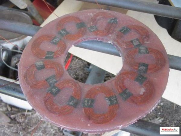
We make a template from plywood - for marking for magnets.


The photo shows a template and one of the brake discs (future rotor).

We arrange 12 magnets measuring 2.5 x 5 cm and 1.3 cm thick according to the prepared template.

We fill the rotor with polyester resin, and when the resin dries, the rotor is ready for use.

This is what our almost completed hydroelectric power station looks like complete with a generator.

Photo from the other side. Under the aluminum cover there are two bridge rectifiers from a 3-phase alternating current to permanent. Ammeter scale – up to 6A. In this condition, when the air gap between the magnetic rotors is reduced to the limit, the machine produces 12.5 volts at 38 rpm.
In the rear magnetic rotor, there are 3 tuning screws to adjust the air gap, so that the generator can spin faster as needed, hoping to find the optimum.

In their spare time, 17 people took part in the creation of the hydroelectric power station.

Let's start making fasteners; to do this, we first clean all the rust from the sheet metal and corners, prime and paint, this is of course not necessary, but it’s more beautiful this way, and it will look marketable.

Our generator with a water wheel is ready, all that remains is to install it!
It would be nice to build a splash screen for the generator that would rotate with the wheel, but we haven't found one yet. suitable material. Therefore, we decided to do this later, if the hydroelectric power station starts working.

Another photo of the generator with a water wheel. The nozzle has not yet been installed, it is in the back of the body and we will install it soon.

The photo shows the place where we want to put it. A 4-inch pipe comes out from the bottom of the dam, about a 3-foot drop. We only take a small part of the water flow.

This is our old micro-hydroelectric power station, which worked for 2 years, including winters. It was enough for 1 Ampere (12 Watts) or so. This is a squirrel wheel, with a belt drive to the engine from a computer streamer from Ametek. Belt tension is critical to successful operation and must be adjusted frequently. We hope we've built something better than this.

Here is our hydroelectric power station in place, we are setting it up. Finally, we arrive at the theoretically predicted parameters: the best result is obtained when the water enters for 10 hours rim, and leaves around 5 o'clock.

It's working! The output is about 2 Amps (1.9 to be exact). It is not possible to increase the current. The adjustments are not easy to make - each movement of the wheel requires a corresponding movement of the nozzle, and vice versa. We can also change the air gap and change the connection from star to delta. The result is clearly better for the star - the power is higher than for the triangle at the same speed. We ended up going with a chainring with 1.25 inches of clearance (quite a lot).

The machine can be made a little cheaper by using less powerful magnets and a smaller air gap... or it can produce more current with the same magnets, less gap and coils with more turns. We'll do this someday. In the meantime, the wheel produces 160 rpm at Idling, 110 rpm under load, producing 1.9 A x 12 V.
We had a lot of fun, it was a lot of fun, and the mini-hydroelectric power station works well. We still need a screen for the generator - the river is full of magnetite sand! Every few hours you have to clean the magnetic rotors from sand build-up. You need to either install a screen or attach a couple powerful magnets at the entrance to the pipe.
Based on materials from the site: Otherpower.com
Option #1
Homemade Cable Garland mini-hydroelectric power station - perfect solution to obtain affordable and inexpensive electricity if there is a small river near your place of residence.
The design of a garland cable mini-hydroelectric power station is based on the rotation of the cable in the river bed.
The first designs of an autonomous simple hydroelectric power station were implemented long ago by individual craftsmen half a century ago. Back in the 50s, Radio magazine published information about a garland hydroelectric power station, made in tin cans and with a generator from a car!
Fig.1. Appearance DIY rope garland of a mini-hydroelectric power station.
How to make a cable garland hydroelectric power station with your own hands?
The figure below shows a diagram of the design of a simple cable garland mini-hydroelectric power station with a turbine-cable hydraulic drive, which rotates from the flow of the river.
Fig. 2 Scheme and principle of operation of the Garlyandnaya mini-hydroelectric power station
1. Bearing, 2. Support, 3. Metal cable, 4. Hydraulic wheel (turbine),
5. Electric generator, 6. Upper river level, 7. River bed.
As hydraulic wheels (rotors), in a cable hydraulic drive of a mini-hydroelectric power station, you can use several “impellers” made of a thin metal sheet, about half a meter in diameter, similar to a children’s toy - a propeller made of a square sheet of paper. It is advisable to use a regular shaft as a flexible shaft. steel rope with a diameter of 10...15 mm.
Approximate calculations show that from such a cable hydroelectric power station, you can get up to 1.5...2.0 kW from one hydrowheel, with a river flow of about 2.5 meters/sec!
If supports 2 with bearings 1 and an electric generator 5 are installed on the bottom of the river, and the bearings with the generator are raised above the river level, and this entire structure is placed along the flow axis, then the result will be practically the same. This scheme is appropriately used for very “narrow rivers” but with a depth of more than 0.5 meters. Thermal energy in such a hydroelectric power station can be obtained by connecting electric heaters to an electric generator.
The rotors of a hydroelectric power plant garland are, as a rule, located in the core of the flow (at 0.2 depths from the surface in summer and 0.5 depths from the ice surface in winter). The depth of the river at the site where the hydroelectric garland is installed does not exceed 1.5 m. If the river depth is more than 1.5 m, it is quite possible to use rotors arranged in two rows.
The emergence of dachas and even farms on waste lands remote from the power grid, the galloping rise in prices for fuel and electricity have brought to life the old ideas of autonomous power supply with the widespread use of natural energy from the sun, wind and water. In particular, interest in mini- and micro-hydroelectric power stations has increased.
Two of these hydroelectric power stations are acceptable for building on your own: a micro-hydroelectric power station with your own hands and a floating, dam-free mini-hydroelectric power station. Next in line are designs, the prototype of which was the free-flow (model 1964) garland hydroelectric power station of V. Blinov.
Dudyshev V.D.
Option No. 2
The hydroelectric power plants that will be discussed are free-flow, with a rather original turbine made of so-called Savonius rotors, strung on a common (maybe flexible, composite) working shaft. They do not require dams or other large-scale hydraulic structures for their installation. They are able to work with full efficiency even in shallow water, which, combined with the simplicity, compactness and reliability of the design, makes these hydroelectric power stations very promising for those farmers and gardeners whose plots of land are located near small watercourses (rivers, streams and ditches).
Unlike dams, free-flow hydropower plants, as is known, use only the kinetic energy of flowing water. To determine power there is a formula:
N=0.5*p*V3*F*n (1),
N - power on the working shaft (W),
- p - density of water (1000 kt/m3),
- V - river flow speed (m/s),
- F - cross-sectional area of the active (submersible) part of the working body of the hydraulic machine (m2),
- n - energy conversion efficiency.
As can be seen from formula 1, at a river speed of 1 m/s, per square meter of cross-section of the active part of the hydraulic machine, ideally (when n=1) there is a power equal to only 500 W. This value is clearly small for industrial use, but is quite sufficient for a farmer’s or summer resident’s subsidiary plot. Moreover, it can be increased through the parallel operation of several “hydroenergy garlands”.
And one more subtlety. The speed of the river in its different sections is different. Therefore, before starting the construction of a mini-hydroelectric power station, it is necessary to determine the energy potential of your river using a simple method. Let us only recall that the distance traveled by the measuring float and divided by the time it passes will correspond to the average flow speed in this area. It should also be noted: this parameter will change depending on the time of year.
Therefore, design calculations should be made based on the average (over the planned period of operation of the mini-hydroelectric power station) river flow speed.
Fig.1 Savonius rotors for homemade garland mini-hydroelectric power plants:
a, b - blades; 1 - transverse, 2 - end.
Next, you need to determine the size of the active part of the hydraulic machine and its type. Since the entire mini-hydroelectric power station should be as simple and uncomplicated as possible to manufacture, the most suitable type of converter is the Savonius rotor of the end design. When working with complete immersion in water, the value F can be taken equal to the product rotor diameter D by its length L, and n=0.5. The rotation frequency f is determined with an accuracy acceptable for practice using the formula:
f=48V/3.14D (rpm) (2).
To make the hydroelectric power plant as compact as possible, the power specified in the calculation should be correlated with the actual load, the power supply of which should be provided by the mini-hydroelectric power station (since, unlike a wind turbine, the current will be continuously supplied to the consumer network). As a rule, this electricity is used for lighting, powering the TV, radio, and refrigerator. Moreover, only the latter is constantly put into operation throughout the day. The rest of the electrical appliances work mainly in the evening. Based on this, it is advisable to focus on the maximum power from one “hydroenergy garland” of about 250-300 W, covering the peak load with a battery charged from a mini-hydroelectric power station.
The transmission of torque from the working shaft of a hydraulic power plant to the pulley of an electric generator is usually carried out using an intermediate transmission. However, this element, strictly speaking, can be excluded if the generator used in the micro-hydroelectric power station design has an operating rotation speed of less than 750 rpm. However, you often have to refuse direct communication. Indeed, for the vast majority of generators domestic production the operating rotation speed at the start of power delivery is in the range of 1500-3000 rpm. This means that additional coordination is needed between the shafts of the hydropower plant and the electric generator.
Well, now that the preliminary theoretical part is behind us, let’s look at specific designs. Each of them has its own advantages.
Here, for example, is a semi-stationary free-flow mini-hydroelectric power station with a horizontal arrangement of two coaxial, rotated 90° relative to each other (to facilitate self-starting) and rigidly connected transverse-type Savonius rotors. Moreover, the main parts and components of this homemade hydropower plant are made of wood as the most affordable and “obedient” building material.
The proposed mini-hydroelectric power station is submersible. That is, its supporting frame is located across the watercourse at the bottom and is strengthened with guy ropes or poles (if, for example, there are walkways, a boat dock, etc. nearby). This is done in order to avoid the structure being carried away by the watercourse itself.
Fig.2 Submersible mini-hydroelectric power station with horizontal transverse rotors:
1 - base spar (beam 150x100, 2 pcs.), 2 - lower cross member (board 150x45, 2 pcs.), 3 - middle cross member (beam 150x120, 2 pcs.), 4 - riser (round timber with a diameter of 100, 4 pcs. .), 5 upper spar (board 150x45, 2 pcs.), 6 - upper cross member (board 100x40, 4 pcs.), 7 - intermediate shaft (stainless steel, rod with a diameter of 30), 8 - pulley block, 9 - constant generator current, 10 - “gander” with a porcelain roller and two-core insulated wire, 11 - base plate (200x40 board), 12 - drive pulley, 13 - wooden bearing assembly (2 pcs), 14 - “hydroenergy garland” rotor (D600, L1000, 2 pcs.), 15 disk (from boards knocked into a shield thickness 20-40 mm, 3 pcs.); metal elements fastenings (including braces, hubs of outer discs) are not shown.
Of course, the depth of the river at the installation site of the mini-hydroelectric power station should be less than the height of the support frame. Otherwise, it is very difficult (if not impossible) to avoid water getting into the electric generator. Well, if the place where the mini-hydroelectric power station is supposed to be located has a depth of more than 1.5 m or there is a large amount of water and flow speed that varies greatly throughout the year (which, by the way, is quite typical for snow-fed watercourses), then this design It is recommended to equip with floats. This will also allow it to be easily moved when installed on a river.
The supporting frame of a mini-hydroelectric power station is a rectangular frame made of timber, boards and small logs, fastened with nails and wire (cables). Metal parts of the structure (nails, bolts, clamps, angles, etc.) should, if possible, be made of stainless steel or other corrosion-resistant alloys.
Well, since the operation of such a mini-hydroelectric power station is often possible in Russian conditions only seasonally (due to the freezing of most rivers), then after the expiration of the operation period, the entire structure pulled ashore is subject to thorough inspection. Rotten ones are replaced in a timely manner wooden elements, rusted metal parts, despite the precautions taken.
One of the main components of our mini-hydroelectric power station is a “hydroenergy garland” of two rigidly fixed (and forming a single unit on the working shaft) rotors. Their disks can be easily made from boards 20-30 mm thick. To do this, making a shield out of them, use a compass to build a circle with a diameter of 600 mm. After which, each of the boards is cut according to the curve obtained on it. Having knocked the workpieces together on two strips (to give the required rigidity), they repeat everything three times - according to the number of required disks.
As for the blades, it is advisable to make them from roofing iron. Or better yet, from cylindrical stainless containers (barrels) of suitable size and cut in half (along the axis), in which agricultural fertilizers and other aggressive materials are usually stored and transported. In extreme cases, the blades can be made of wood. But their weight (especially after a long stay in water) will increase significantly. And this should be remembered when creating mini-hydroelectric power plants on floats.
Spiked supports are attached to the ends of the “hydroenergy garland”. Essentially, these are short cylinders with a wide flange and an end slot for a key. The flange is attached to the corresponding rotor disk with four bolts.
To reduce friction, there are bearings located on the middle crossbars. And since ordinary ball or roller bearings are unsuitable for working in water, they use... homemade wooden ones. The design of each of them consists of two clamps and insert boards with a hole for the passage of a tenon support. Moreover, the middle bearing shells are positioned so that the wood fibers run parallel to the shaft. In addition, special measures are taken to ensure that the insert boards are firmly fixed against lateral movement. This is done using tightening bolts.
Fig.3 Sliding bearing assembly:
1 - crimp bracket (St3, strip 50x8, 4 pcs.), 2 - middle frame cross member, 3 - crimp insert (made of hard wood, 2 pcs.), 4 replaceable insert (made of hard wood, 2 pcs.) , 5 - M10 bolt with Grover nut and washer (4 sets), 6 - M8 stud with two nuts and washers (2 pcs.).
Any automobile generator is used as an electric generator in the micro-hydroelectric power station under consideration. They produce 12-14 V DC and can be easily connected to both battery and electrical appliances. The power of these machines is about 300 W.
Quite acceptable for self-made and the design of a portable mini-hydroelectric power station with a vertical arrangement of a “garland” and a generator. Such a hydroelectric station, according to the author of the development, is the least material-intensive. The supporting structure of the installation, which fixes its position in the river bed, is a hollow steel rod (for example, from pipe sections). Its length is chosen based on the nature of the bottom of the watercourse and the speed of the flow. Moreover, such that the sharp end of the rod, driven into the bottom, would guarantee the stability of the mini-hydroelectric power station and its non-disruption by the current. Additional use of stretch marks is also possible.
Having determined the active surface of the rotor using formula (1) and measuring the depth of the river at the installation site of the mini-hydroelectric power station, it is easy to calculate the diameter of the Savonius rotors used here. To make the design simple and self-starting, it is advisable to make a “hydroenergy garland” of two rotors connected so that the blades of the first are offset by 90° relative to the second (along the axis of rotation). Moreover, to increase operating efficiency, the structure on the side of the oncoming flow is equipped with a shield that plays the role of a guide vane. Well, the working shaft is mounted in the sliding bearings of the upper and lower supports. In principle, for a short period of operation of a mini-hydroelectric power station (for example, on a hiking trip), large-diameter ball bearings can be used. However, if there is sand or silt in the water, these units will have to be washed in clean water after each use.
Rice. 4 Mini-hydroelectric power plants with vertically arranged end-type rotors:
1 - support rod, 2 - lower bearing assembly, 3 - "hydroenergy garland" disk (3 pcs.), 4 - rotor (D600, 2 pcs.), 5 - upper bearing assembly, 6 - working shaft, 7 - transmission, 8 - electric generator, 9 - “gander” with a porcelain roller and two-core insulated wire, 10 - generator mounting clamp, 11 - movable guide panel; a, b - blades: the braces at the upper end of the support rod are not shown.
The supports are bolted and welded to the rod, depending on the weight of the “hydroenergy garland” and the need to disassemble it into parts. The upper end of the working shaft of the hydraulic machine is also the input shaft of the multiplier, which (as the simplest and most technologically advanced) can be used as a belt one.
The electric generator is again taken from a car. It is easy to attach it to the support rod with a clamp. And the wires themselves coming from the generator must have reliable waterproofing. In the illustrations, the exact geometric proportions of the intermediate transmission are not shown, as they depend on the parameters of the specific generator you have. Well, transmission belts can be made from an old car inner tube, cutting it into strips 20 mm wide and then twisting it into bundles.
For power supply to small villages, a garland mini-hydroelectric power station designed by V. Blinov is suitable, which is nothing more than a chain of barrel-shaped Savonius rotors with a diameter of 300-400 mm, attached to a flexible cable stretched across the river. One end of the cable is attached to the hinged support, and the other through a simple multiplier to the generator shaft. At a flow speed of 1.5-2.0 m/s, the chain of rotors makes up to 90 rpm. And the small size of the elements of the “hydroenergy garland” makes it possible to operate this micro-hydroelectric power station on rivers with a depth of less than one meter.
It must be said that before 1964, V. Blinov managed to create several portable and stationary mini-hydroelectric power plants of his own design, the largest of which was a hydroelectric power station built near the village of Porozhki (Tver region). A pair of garlands here drove two standard automobile and tractor generators with a total power of 3.5 kW.
MK 10 1997 I. Dokunin
Option No. 3
Homemade hydroelectric power station (HPP) on a small river without a dam.
It is known that electricity is generated by a generator whose shaft rotates the engine. The hydroelectric power plant engine is designed simply: racks with two crankshafts A and B are mounted on a frame made of logs (see Fig. 3).
Each shaft has three elbows, the angles between which are 120°. The crankshafts are connected by rods to which the blades are attached. In Figure 1 you see that at the moment all the blades of rod B are at the bottom, they are immersed in water and under its pressure they move back (to the right). The blades move the rod, and the rod, in turn, turns the crankshafts. As soon as the knees connected by this rod begin to rise up, the blades of the rod G are immersed in the water. Now they begin to work. Then the blades of rod D will begin to work. By this time, the blades of the first rod B will pass above the surface of the water and sink into the water again. This is how the engine of the Login power plant will work.
If you attach a pulley to the end of one of the crankshafts and connect it with a belt drive to the pulley of a DC generator, the generator will begin to generate electricity. And if you attach a connecting rod to the drive pulley and connect it to the pump, the engine will pump water to the school plot, to your garden.
The power of the engine depends not only on the speed of water flow, but also on the number and area of the blades, that is, on the geometric dimensions of the engine itself. And it can be made of any size, proportionally increasing or decreasing the size of its parts.
Rice. 1 Basic dimensions of parts of a mini hydroelectric power station without a dam.
We provide drawings of an engine that, at a water flow speed of 0.8-1 meter per second, will rotate the generator from passenger car. The voltage generated by the generator is 12 V, and the power is up to 150 W.
Fig.2 The main components of a homemade hydroelectric power station without a dam.
Before you start building a hydroelectric power station, pick up a generator in a workshop or store that sells car parts. Prepare materials: boards, small diameter logs, steel wire, fasteners. Select the location where the power plant will be located. It is advisable that this be a straight section of the river. Here you need to determine the flow speed. It's done like this. On a selected area 15-20 meters long, mark two transverse sections. After this, using a small float, such as a piece of wood, determine the speed of the water flow. The float should be thrown into the water slightly above the upper target and, watching it, use a stopwatch to count the time the float passes from the upper target to the lower one. You need to make 10-15 such measurements, throwing the float further, sometimes closer to the shore, and based on the measurement results, calculate the average speed of the river flow. If it lies within 0.8-1 m/s, feel free to start construction.
Fig.3. Crankshafts of mini hydroelectric power stations without a dam.
How to make the most complex parts of a mini hydroelectric power station without a dam. Mini Gas crankshaft without dam.
It can be made from a solid steel rod with a diameter of 16-20 mm. But it is easier to make it prefabricated (Fig. 3). First, cut parts 1, 2, 3 and 4 from the rod. Make the cheeks of the knees from a steel strip 5 mm thick. Saw squares at the ends of the rods, and at the cheeks - square holes. After connecting the parts, the squares are riveted. First, assemble parts of the crankshaft “a” and “b” (see Fig. 3). Then you need to mark and cut out squares on the free ends of rods 2 and 3 so that the middle bend (after assembly) is located at an angle of 120° with respect to the outer ones.
Rods with blades of a mini-hydroelectric power station without a dam.
Transmission device for mini-hydroelectric power station without a dam.
The crankshaft, and therefore the drive pulley, will rotate at a speed of approximately one revolution every two seconds. The generator can produce electricity at 1000-1500 rpm. To obtain such a number of revolutions on the generator, you need a transmission of pulleys of different diameters (see figure).
Grooved pulleys are made of 5 mm thick plywood. For each pulley, cut out five circles. They are knocked down with nails or tightened with screws. The drive pulley, which is firmly attached to the end of the crankshaft, must have a diameter of at least 700 mm. Two intermediate ones are nailed to each other and loosely put on the axle. They should rotate easily on this axis. If the rotation speed of the drive pulley is 30 revolutions per minute, then the diameter of the small intermediate pulley can be taken equal to 140 mm, and the large one - 600 mm. Then the generator pulley (60 mm in diameter) will rotate at a speed of 1500 rpm. At other speeds of the drive pulley, the diameters of the intermediate pulleys will be different. A labor teacher will help you calculate their sizes.
Drive belts for mini-hydroelectric power plants without a dam.
The transmission pulleys are connected by drive belts. To ensure that the belts are always well tensioned, make them from a rubber band. Cut an old car inner tube into long strips. Twist each ribbon into a rope and glue the ends together rubber glue and tie tightly with twine.
Adjustment of mini-hydroelectric power station without a dam.
After assembling the mechanism, check whether the rods rotate freely. While turning the drive pulley by hand, notice which rod is preventing the crankshafts from rotating. After this, remove the barbell and enlarge one of the holes for the neck of the knee so that it becomes slightly oblong.
V. Kivonosov, V. Slashilina
Option No. 4
Small, inexpensive, damless hydroelectric power plants (HPPs) can be built on most rivers. The power of such power plants is small, but sufficient to electrify a home or even a small village.
On rivers with a flow speed of 0.8 meters per second or more, a new type of damless hydraulic motor can be installed. The operating principle of this engine is clear from the attached drawings and diagrams.
Under the pressure of water, the blades move the rods, the movement of which causes the crank to rotate. A pulley sits on its shaft.
The rotation of the pulley is transmitted to the generator. Engine power depends on the speed of water flow.
In places where the flow speed is low, it is necessary to narrow the river bed. The design of a hydraulic motor, for example 3.5 kilowatts, is so simple that it can be made in any school club or workshop.
M. Login
An interview from Moscow journalist Andrei Polyakov, who kindly provided us with his material, which due to his workload he could not post on his website. The conversation may be interesting to someone, so we posted it here, adding photos and sketches that appeared in the video.
The conversation took place in the summer of 2011.
- Micro hydroelectric power station from an air pump (snail).
- Homemade Stepper Low-speed generator on permanent magnets, without gearboxes and rolling bearings, at a mere cost.
- Turbine made of Wood. Is it really real? Sketches.
- How to Transmit mechanical energy over 100 - 5,000 meters without electricity?
- How and what to make a generator from in extreme conditions of network outage?
- The film “Village of Water Mills” is a hint about Harmony with Nature.
- Gravity is a source of energy. Scheme. It's simple.
Erast, at what stage is work on your homemade micro hydroelectric power station now? Will the moment of the first test come soon?
We are just doing it for now. We do what is called “a teaspoon per hour” because of the abundance of worries that also cannot be pushed aside. Welding work is 95% complete. In other words, the “machine” already exists. All that remains is to stick around with little things, and with them, as you know, there is more fuss than with an array of iron. This includes cleaning, painting and drilling, riveting, assembly with bolts, installation of magnets, windings with semiconductors.
What is this product in general and what is its operating principle?
Simply put, this is an ordinary centrifugal-type air pump, 1.2 meters in size, of which there were and are a great many in enterprises and collective farms, popularly or in the slang of technicians called a “snail”. Its body is slightly reshaped, the outlet opening is opened wider, and its operation, already as a micro-hydroelectric power station or hydraulic turbine, is designed as if backwards. That is, the entrance and exit for air change places, the exit window has become an entrance-socket for the incoming water flow of the river. The body is located lying down, which is very advantageous in shallow waters and on small rivers. Water comes out along the shaft, below and above from two holes cut in both decks. The shaft has stainless steel tips.
An impeller from the same pump with a slightly larger diameter is welded to the shaft and inserted into the housing of this former pump. With this arrangement, a centripetal vortex is formed, which rotates the impeller one and a half to two times faster. Moreover, this acceleration is also helped by the flaps fixed inside, redirecting the flow to the impeller at a more favorable angle, and even with the formation of vortices in the gaps between themselves and the impeller flaps. Thus, the centrifugal air pump became a centripetal type hydraulic turbine, presumably with a power of 0.2 - 0.5 kW. And with even greater current strength it can be “stretched” by 1 kW.
Photo 2. 
What is the point of this alteration and what do we get as a result?
We have an energy source made at extremely low cost. One average pension is enough at cost to produce it. Its power, presumably, should be about 200-500 Watts, based on powering the walkie-talkie, emergency lighting, charging batteries, video-audio equipment, computer, etc. It is transparent, installed and removed by one or two people. Moreover, this is an example of implementation on just one axis of rotation, in two assemblies of birch bearings. Everything is cooled and lubricated with water. Without any gearboxes, pulleys or belts, without high-tech bearings that require lubrication from petroleum products and protection from water with all kinds of seals. Birch can be soaked or boiled in oil, drying oil, rosin, wax, paraffin. Impregnate with any acceptable water-repellent compound. This was precisely the main feature.
A ring 600 mm in diameter, with thirty permanent magnets, should be attached to the impeller. EMF (Electromotive Force) occurs in six or nine windings filled with resin to insulate from water. It turns out similar stepper motors, low-speed multiphase (6 or 9 phase) generator. Then, through diode bridges, everything is output to two cable wires and, already on shore, it is finally straightened to direct current. And then “do with him what you want.”
So we are talking about the fact that this thing should work at any time of the year?
Yes. At least under the ice. And almost all year round. But apparently it will be necessary to clean the grass and twigs from sediment and remove them from under the ice before the spring ice drift. Autumn slush - fine ice during the first frosts - is also of course not needed. In general, a couple of months a year fall outside the year of operation.
On what waters? On small rivers or what? That is, in a small current?
It is designed for a speed of about 5-8 km/hour. Not less. And here this is exactly the range in areas up to 3-5 meters deep on the core.
How can we call it “small”? Look, when you stand at Kazyr, such power rushes, it takes your breath away. I just want to “come to an agreement” with him, and then harness him somehow...
Photo 3. 
It's clear. Using the example of this micro hydroelectric power station, can more powerful ones be created?
Yes. More powerful ones can be created. But I wouldn’t go down this path at all. I have a blank from an even larger pump, designed for 1-3KW. The body and its “native” impeller. I brought it once for the same purpose. But now I’m thinking, is it worth cutting it? Because I want to stop making welded structures.
And what we are doing now is smaller, at 200-500 watts. is done only to show that it is possible and it works. Because some people don’t really believe in that either. And then, if we repeat such a thing, then in a tree. Entirely made of wood.
The main trick is this. To show that this is being done, well, practically for free. We calculated so that it would be possible to install even permanent magnets from household equipment by removing them from meters or from electromagnetic relays(starters) transformer iron, winding wires from anywhere, selecting the cross-section and number of turns, winding them, filling them with bitumen. And it will work. There will be no magnets - we will make excitation windings. If necessary, we can even make a turbine out of a log. Let's choose something more even, drill with drills or feather drills, drive the blades on wedges (under the right angle) and get a mechanical drive.
There are plenty of ideas and ready-made developments. We can even build a swinging blade and transfer energy by reciprocating motion to the shore with a simple galvanized (or even aluminum) wire from an overhead wire from high-voltage poles. And then use it for the movement of the sawmill frame or convert it into rotation of the machine parts. This was successfully used in past centuries and in Holland, for example, it has survived to this day, after 350-400 years.
Photo 4. 
A separate topic is the use of winds. For all their inconstancy, they have great strength and using their great energy in mechanical form You can accomplish a huge amount of work in just an hour or two.
Everything is based on the idea of “how to do it without money or purchases.” In the most critical case. And not because it is impossible now, but because one day it may become impossible. Turn off the switch - extreme weather ensues. And the switch is dying. Look, our “Shusha” has already given a sign. They fussed, ran around, and then calmed down. Almost all. But there was a sign!
The word “wood” was heard here, but everyone will say “how will wood work in water? Will it still get wet?”
Great question! And quite natural given our upbringing in the society in which we were born and raised. But imagine that we were born in the 17th century. Would we have such a question? It would never have occurred to me! Everything on the tree worked there. And in water and in fire and in foundries and forges...
Photo 5. 
Ships were tossed and chattered in the seas for 30 years. The Japanese (and Chinese) still have water in the provinces for washing in wooden barrel heated over an open fire, similar to the school experiments of our childhood (when water was boiled in a paper cup). The water wheels themselves, which powered almost all the machines and equipment, were made of wood and worked in water. Barrels without water dry out and begin to leak. There are laws of physics and “secrets” of carpentry that not only deal with wetting and swelling, but even use this to increase the strength of the entire structure. Many rocks do not rot in water and whirlwinds and can even survive metal.
Rice. 6. 
In addition, if we mention vortices, it is useful to know that they work well in devices made of diamagnetic materials. That is, made of non-magnetic material. What exactly does the tree have to do with it? best option. Burnt clay and stone are also good. They are the ones who can catalyze processes in water. Look at the rivers. It is these materials that water comes into contact with. And if you are careful and observant, you can see the seemingly supernatural behavior of water in Nature.
But that's not the point. This is all interesting, but not the main thing yet. We are considering the topic from the point of view of so-called extreme conditions, this is the notorious word for emergency situations. The upcoming circumstances will not ask us whether we want to construct in wood or consider it junk. They will simply leave us with one tree and several iron stashes around the yards. That's all. The enema will wash away all our dreams and delusions. But we really need to understand what we will be left with.
We must boldly admit that we are sick with technocracy. And it will be our destruction. Especially in these times. Well, for example, our mega-toys were washed away or blown away, something collapsed there. Well, this is actually happening these days. Here and there. Collapses, sinks, burns...
The earth is alive. She wants Harmony. She breaks our toys. They interfere with her life and threaten to destroy her, while we, with serious faces, run across its surface with all sorts of shooters, and do big things, either under water or under her skin. Yes, we tormented Mother Earth with our stupid games! Especially with your negative emotions and aggression.
And now its Harmony is approaching. Wow! And she feels good... Silence. Space sounds. And for us there is an emergency. Extreme conditions in the middle of Great Harmony. Absurd and that's all.
But I understand perfectly well that it is simply impossible to convey these things to most people. The psychology of perception has changed too much. I was treated for habitual thinking for about 10 years.
Photo 7. 
After watching Akira Kurosawa's short film "Watermill Village" (from the "Dreams" series), I was very inspired. I felt to the depths of my soul HOW HARMONIOUS IT IS! And only 10 years later I began to understand simple words, said by the elder. And then I still had to “cure” from the desire to make everything from purchased welded pipes.
Photo 8. 
I've been very lucky in life. Reality presented me difficult lessons. It took me eight years to create this micro-hydroelectric power plant of ours. He collected the iron (while the collective farms collapsed, and their remains had not yet been consumed). And for a long time I could not begin to do anything. There were no opportunities. But none. Such languor of the idea forced us to hone everything down to the smallest detail. Learn not to demand from Reality and from people. Don't get attached to the result.
Later, he started, sacrificing a lot in his life. Few people know anything about this. I advanced by 70%. And again there was a break of one and a half to two years. And all this led to a simple thought: if I had immediately made a turbine in a tree, I would have done it long ago. On your own home workbench. This all helped me understand that this is the only way it should be. Due to upcoming conditions. For a year I toiled with the thought “how should this be arranged?” It took me a long time to find a solution.
One day I lay down on my bed and began to meditate on a completely different topic. How, I wonder, did these ancient Greeks soften basalt and cast statues from it? I remember a friend told me.
“Took off” something. Then, since things were going crazy, I started thinking about a turbine made of wood. Twisted, spit... And Ooooh! Oh! Here I “saw” her in all her glory. And I was so inspired that I really saw her beautiful. It is beautiful!
The electronic drawing shows the assembly diagram. This is, of course, a pitiful semblance of the imaginary, but I still think it will be understandable.
Rice. 9. 
Absolutely in the likeness of a snail pump. Two decks of shields connected in a tongue and groove are edged with a set of slats, like a cooper's stave. Brought together to two main load-bearing beams with two wire hoops - sixes or belts of the same wood, pulled in with wedges or wire ties. In both decks there are holes for the impeller, similar to the same water wheels. This same rotor is inserted into them onto two beams with bearings. All wood. Only the rotor shafts are made of hex head bolts and threads similar to wood screws. This (without details) is a turbine made of carpentry-assembled wood with elements of a cooper's assembly, just one of several mental developments. Some things are already designed and in the model. The nodes and connections have been worked out.
Photo 10. 
I already mentioned in the last conversation about the period of conditional poverty. Useful thing poverty. She makes you THINK. During my next move, I brought with me an impeller from an even larger air pump (scroll) 250-300 kg. And I began to wonder how I could deal with him now. Shaft 1m. length and 100 mm. in diameter, with 90 kg. the weight had to be pulled out with a huge puller, which is not there, turned on a lathe, and inserted on the other side, welding more parts.
I again ran into money and orders (because I sharpen myself, but I don’t have my own machine and there’s no access nearby either), I ran into turning work, transportation, etc. And then I finally realized that I was doing nonsense and now I don’t need it. I spent so much time and money transporting this rotor so many times, just for the sake of my own epiphany. Been hanging around with him for so many years, trying to turn him into water wheel or a turbine and only now “it came to the giraffe.” And I began to understand more deeply the technologies of the 17th and 18th centuries from the perspective of technologies from the times of the Earth’s transition. I realized that all this hardware of ours is, by and large, unnecessary. It entails welding, with all the connection problems, lack of power in towns and villages, consumable electrodes, disks, turning work, fussing, and essentially MONEY.
If I had money then, the necessary conclusions and insights would not have been made. If I were now offered to live that poverty-stricken period again, but with money, I would refuse. Otherwise I would have sold my insights. Then they could buy them from me. But they are expensive. You can't measure them with money. I simply lived the lessons that still lie ahead for everyone who believes that there will always be money.
And even since we have created some workshops, we can do this in hardware together, on our equipment, chipping in with our pensions and earnings. But this is still a certain complexity. It does not show how to LIVE WITHOUT MONEY and live without technocracy. But I set a goal for myself (I deliberately turned myself in this direction) - to collect possible information, adapt and distribute it widely, to show how something can be done without technocracy. Literally from what WILL REMAIN WITH US AT OUR DISPOSAL and there will be no other. When the hour "H" comes.
And later, having explored the topic of upcoming events on the planet even more deeply, he formed a system or concept of technology and technology of the transition period called “Stalker 2012-17-30”. With a bit of a joke, the decoding of the abbreviation is as follows:
Armageddon Technology System of the Human Concept of Unified Development.
And Stalker is a guide to the unknown, the transcendental, the anomalous, which awaits us all. And if Stalker is a guide, then Stalker technologies will help us “go through” the period of Earth’s transition.
We certainly hope to complete it. There is no miracle. Everything is very simple.
When will this happen?
Now we will wait for spring. Maybe we'll make it earlier. We’ll cut out half a meter of ice with a chainsaw and “fish” for it. But I wouldn’t make any deadlines and I wouldn’t promise anything, especially so. Few of our deadlines come true. Let's live by the process and not the result.
And I can also add: We work with it only because we started it once. In fact, our interest has long been directed to other areas.
Let's touch on this area just. That's what I wanted to talk about.
Yes. These are gravity wheels or the so-called unbalanced wheel principle, which is the simplest and most affordable alternative for any yard or household. The question is controversial, of course, for people who are not initiated, and especially for adherents of the orthodox scientific approach. But those who search in this area have long understood that gravity can do useful work. And we were convinced in practice.
Returning to the topic of the previous conversation, the dogma ABOUT the IMPOSSIBILITY of creating a device with an efficiency higher than 100%, or an engine that turns itself, seemingly without consuming anything, and even produces work, is a false dogma. And those who don’t know about it or don’t believe in it often do everything successfully and everything works for them.
At the end of the second millennium, a lot of contact (channeling) information began to appear, all kinds of references and warnings (in books and other literature) that flows of information about “new” sources of free energy would soon simply pour over the edge into thousands and millions of minds, and suppress they will become simply impossible. Millions of people will receive information on a conscious level and make “their” inventions in real life. Disinformation will also not be able to stop this truly gigantic wave. This is exactly what is happening these days.
Quite legally, there are many sites where, along with misinformation, there are a lot of gravitational wheels exactly similar to those that were presented as not working in books like entertaining physics by Jan Perelman (or other authors). But they work. And there are hundreds of types and principles. Enough video. Turning a blind eye to this, proving to yourself that it is impossible, this is deception, editing, computer graphics, is hiding your head in the sand.
Gravity wheels are the smallest “pawn” that can be sacrificed by giving it to us in order to save the remaining “pieces”. There are more serious developments. And here we can recall the phrase from the New Testament: “But even dogs eat crumbs from their masters’ table” (in another place children). A hungry person will really go through grub. If you are truly hungry, then where does all your pride go? They gave me a piece and thank you. Why should we be picky?
Here's JUST one example: (YouTube - Chas Campbell - Gravity Wheel)
Photo 11. 
One good American guy made a gravity wheel about 3 - 3.5 m in diameter. Below are gearboxes - chain, belt, pulleys and flywheels. The electric generator rotates from them. The video is very “pinched”, but despite low quality we managed to understand that this is a type of unbalanced wheel with a controlled shift of the center of gravity. And naturally, the white disk covers the mechanism that controls the loads. But it is clear that the weights are pale burgundy in color, probably interconnected with a slight play, on the left closer to the center, and on the right further, almost on the periphery. At the top, as they rotate, they rise, and at the stage of movement at the bottom, they also rise. That is, at the top they move away from the center, and at the bottom they are pulled towards it. There is no need to pay attention to the white lines between the outer rim and the inner disk. These are reinforcement elements for rigidity.
Roughly speaking, the loads describe a circle eccentric to the center of rotation of the wheel itself. The rotation goes clockwise. Uncle includes a load of 2.5 - 3.5 kW on the power tool. This is between 3 and 4 kW of mechanical power. It is not so important on which rods (swinging or not) the loads are suspended. The mechanism for managing them is important.
At first, the control mechanism seemed somewhat complex, but workable. And later we came to the conclusion that everything is much simpler.
Rice. 12. 
Here is a drawing from the Do-It-Yourself magazine 15-20 years ago, in an article about water wheels for your own household. Such good old water wheels with rotating plates (blades) began to be used after simple, steam-powered water wheels with static unregulated blades, so that the blades would enter at a more favorable angle, would slap the water less in vain, and in general their efficiency is higher than simple ones. They are already a hundred years old or more.
Rice. 13 
And if we slightly rotate the drawing, remove unnecessary details and add our own, then this is what happens. A direct hint from the past. You can imagine two hubs with spokes, spaced a short distance apart, having a common rim. And a crankshaft passes through both hubs, the middle journal of which is spaced from the main axis (main journals) at a distance of 0.5 from the difference in the position of the loads on the radius. The third, control hub is attached to this middle neck. From it go rods (pushers, rods) to the load coupling units (movable coupling, with play, since points A converge and diverge. One of the rods must be connected rigidly to the hub, the rest must swing.
That's actually the whole mechanism. It is very simple, which many people fail to understand. This raises a lot of controversy. The mind cannot accept the idea that this is simply how it works. "A! Just? - Can't be!" They say it must be difficult. And it is rejected. In fact, “everything ingenious is simple” comes from things like these. Not primitive, but simple.
It is noteworthy that by “random” coincidence(and as the wise say, there are no accidents) the drawing of the Gravitational Wheel was number 13. What does this mean? Mysticism, Rock, Devilishness?
This is Mysticism, but far from rock.
"13"- It has nothing to do with devils and other things, where this is attributed to people who have had this attitude towards the number “13” drummed into them since childhood.
"13" doesn't resonate and is not proportional to any numbers, dimensions and vibration frequencies of this dimension.
IT'S BETWEEN. That is, it symbolizes a transition, a transitional state. It's like "Tone - Semitone" on the keyboard, in music, in color, in sound. So “13″ is the number of TRANSITION. Everything is as it should be.
It's a sign! (Laughing) It's time to GO to Wheels. (Laughter again...)
How else can we move into the future? With a DE-energized socket in your teeth or what?..
Let's return to the turbine. So you can do something like this? Without attracting any large funds. It's still a tree, as far as I understand.
Yes, the fact of the matter is that we want to take the path of not attracting any funds. All we can attract is what we don’t need to attract. It just might speed things up. No more. Maybe we won’t attract anything at all. But will we do it? - Let's see. Maybe we'll find something better.
Because while we were “making” the turbine in a hurry, we had outgrown it. It’s no joke, a year and a half breaks. Time passes, the turbine stops. We involuntarily communicate, consult, learn new things. As long as we live to see the bright moment to take on this, maybe we will outgrow it.
It seems to me that something needs to be brought to the end.
So we are finishing the turbine. It’s not easy, but we jokingly agreed - we work in “retro style.” We joke with each other - imagine, we fly around on saucers, and then we wanted, “let’s build a sailboat or a yacht, a real piece of wood. Let's take a walk, breathe in the fresh wind, the scrapes, the bumpiness. Like once upon a time. In a past life". And we work with the turbine, thinking about something else. Otherwise, those who are expecting a turbine from us and have invested may not understand us if we give up. Here we are trying for the sake of relationships, and not for the sake of a better result.
After all, the main point is that we will be saved, first of all, by trusting, good relationships, selfless help as in our own family, no matter how much we try to implement this. Otherwise, if everyone is for himself, no pieces of iron or wood will save us, no matter how many we make and stockpile. Behind these just a few words lies the main thing. Just one mention, and life depends on it.
Well, you will make a turbine. Of course, she will give you an idea again, but I think you will follow through with it. What a fundamentally new stage can we reach with such gravitational things?
Well, what is 3.5 kilowatts in your own household? In fact, there is no need for more. This is more than excessive habits. Any carpentry machine consumes about 3 kW. This is electrical power. And if we cut out the “generator - wires - engine” link, just like that, the “clack” is cut out. And they did a direct mechanical transmission. Maybe even our own variators. And there are even fewer losses. The yield is greater. Our carpentry machine, made in any way, especially if made using 17th century technology, will run on this power. This is enough to provide for the entire economy. Turn on one or the other alternately and that’s enough. Of course, we are not talking about the mandatory presence of only electric stoves and kettles with irons. Natural fire gives much more health to food than all this rubbish. Perhaps as an exception or a spare addition. And light generally requires little things of energy.
Let's draw conclusions: In principle, by combining these things into a certain system, a separate farm can be energy-closed, self-service, say, along a river of some kind...
Or without a river.
Yes, without a river. And these huge substations are not needed, there is no need to disperse it all. As I understand from what has been said, this can be done by almost any person who is more or less intelligent. For some wheel that was invented a long time ago, there is an engineer, there are people who are ready to do this. All this is quickly done and replenished independently, from materials from Nature. That is, we do not lose anything in any cataclysm, since the electrical mechanisms will not fail.
Yes. Yes. We are considering precisely the moment of life in extreme conditions. We are not currently setting the task of creating an alternative to centralized power supply. We just need to survive. The management circles have done a great job of making their future for themselves. Right? They did everything that was considered necessary for their own salvation. We also have the right to do something for our own salvation. You need communications, lighting, minimal video, audio equipment (if it still continues to work) and mechanics, machines. We need to build, make materials, alternative equipment. We want to live. We are given such a right, right?
A question of quality of life. How exactly to live?
Regardless of system shocks. After all, everyone (if not the blind) sees these shocks.
That is, you are optimistic about the number 111, which is rapidly developing in 2011, a new date has been set for the quantum evolutionary leap. Either 11. 11. 11. Or 05. 11. 11. And that the symbol of salvation 111 is a bus that runs along the route Tayaty - Karatuz, number 111 :-)
The combination of circumstances suggests a lot. But I don’t really stick to it... It may be that we have come to new information and have new experience, this is the manifestation of all these signs.
(An example of the implementation of birch bearings on a pottery machine in 2006.
Photo 14. 
