Electrical installation products from ANAM. Instructions for remote controlled switches General notes on electrical wiring
It would seem a trivial question - how to connect a switch to control lighting devices. However, for many novice home craftsmen who are arranging their residential property for the first time and strive to do everything on their own as much as possible, this operation can cause complications. Moreover, various variations of connection schemes are possible, from the simplest to the very complex.
The variety of switches on sale is extremely large. But mainly these differences relate to the external design of the devices and the “mechanics” of switching. And so, in all series produced by leading manufacturers, the approximate similarity of the “sets” of models based on the principle of switching contacts is still observed. In this article we will look at where, when and how different types of switches are connected.
Variety of switch models
What is a switch and where is it installed?
A switch is an electrical switching device designed to control the closing and opening of the power circuit going to the lamps. Some household appliances, for example, a permanently installed fan, can also be connected through it.
Let's say right away about most important rule!
The switch is always placed on a phase wire break. Yes, the power circuit can also be controlled through a break in the neutral conductor. And quite a lot of “masters” are guilty of this - they say there is no difference. But this is a blatant violation of operational safety requirements. The meaning here is simple and clear - if the switch breaks the circuit, then there should be no life-threatening phase voltage on the device connected through it. That is, for example, replacing a burnt-out lamp in a lamp will not be accompanied by the possibility of electric shock.
And one should not hope that this issue is not so serious. Neglecting simple rules of electrical installation is always fraught with serious consequences.
How big is the risk of electric shock?
The answer is clear – extremely large! A 220-volt household network is quite capable of causing severe electrical injuries, sometimes incompatible with life. If there is no understanding of this issue, then you should not undertake electrical installation work yourself. To begin with, carefully read the special publication on our portal, which describes in detail the dangers of electric shock.
Types of switches by design
Let's leave aside the external design of these devices - here each manufacturer is trying to attract the buyer original design. So you always have the opportunity to choose a set of sockets and switches made in general style, most suitable for the planned decoration of the room. Let's focus on more fundamental issues.
Built-in and surface-mounted models
In modern apartments and houses, in the vast majority of cases, built-in models are used. Their use is possible only with hidden wiring. The switch is installed in a “socket” pre-arranged in the wall, in which a standard socket box with a diameter of 68 mm is most often used.

It is clear that the installation of such switches requires quite extensive preparatory work. Moreover, the laying of the necessary cables and wires must be thoroughly thought out in advance. But hidden, well-executed wiring is safer to use and does not interfere with any chosen wall decoration.
How to plan electrical wiring in a house or apartment and install it
The task is of primary importance and increased complexity. When performing these very large-scale and labor-intensive activities, it is necessary to strictly follow the established rules and technological recommendations. This is described with all the details in a special publication on our portal “Do-it-yourself electrical wiring in the house.”
Surface-mounted switches are mounted on the wall surface. This greatly simplifies their installation, and they can be used with both open and hidden wiring.

Such devices are not always appropriate in the interior, as the walls protrude too much beyond the surface. But where this issue is not fundamental, such switches can greatly simplify the task. They are often used in utility or utility rooms. Many of these models have an increased class of housing protection, and can easily be installed outdoors or indoors with high humidity.

However, there are fans of emphatically original design of living rooms, using open wiring made in retro style. For this purpose, there are also entire lines of overhead electrical devices - sockets and switches.
Number of keys
This difference is immediately visible - there can be one, two, three keys, and in rare cases even more. Obviously, such switches can be used to control several light sources or several groups of lamps on one luminaire.
A very common example is a two-key model installed in front of the entrance to the bathroom and toilet, or a three-key model if a corridor or kitchen is also added here. Another “classic” option for using a two-key switch is to separately control groups of lamps of one multi-arm chandelier in the living room.

The convenience is clear - there is no need to prepare two (or more) sockets with sockets for several switches - you can often limit yourself to one.
It should be correctly understood that the number of keys does not at all uniquely determine the functionality of the switch. In addition to conventional devices that work only to close and break a circuit, there are pass-through and cross-type devices, which, in turn, can also have one or more keys. This will be discussed in more detail below.
Switch housing protection class
All electrical devices are divided according to the degree of protection from contact with current-carrying parts of solid objects (including dust) and moisture (water). Depending on the expected operating conditions of the circuit breaker, a model that meets these criteria should be selected.
The security class is indicated letter designation IP followed by a two-digit number. The first number indicates the degree of protection against solid particles and dust, and can be from 0 to 6. The second number is an indicator of protection from water ingress - from 0 to 9. The higher the number, the higher the protection.
In ordinary living rooms, where there cannot be too much humidity and dust, it is quite possible to use IP20 class switches. Nothing prevents us from installing more secure ones here, but this is reflected in the cost. But for the kitchen, for example, it’s worth choosing a model of IP44 class - here there are enough fumes, and the possibility of splashing water cannot be completely excluded.

The requirements are even higher if the switch is installed in a bathhouse, shower room, or unheated damp room. Here it is better to use models with a class of at least IP45. Well, if the installation is supposed to be outdoors, that is, direct exposure to atmospheric precipitation is possible, then the optimal model seems to be no lower than IP55, 56, 66 - extra insurance will never hurt in these matters.
Differences by terminal type
Most switches use regular screw terminals to connect wires. The stripped end of the wire is inserted into the socket (hole), and then using a screwdriver, the screw is tightened to ensure reliable clamping in the terminal. Solid wires can be tightened directly into the terminals. Stranded - first they are tinned, or, what is simpler, a terminal lug is put on them and crimped.

Many modern models use spring terminals. There are no screws on them - after the prepared end of the wire is inserted all the way into the hole, the terminal is clamped automatically, ensuring reliable contact. Convenient and fast, although some electricians are still skeptical about the durability of such connections, preferring to work with conventional screw terminals.
Availability of light indication
A convenient feature that allows you to avoid fumbling around the wall with your hand in the dark. The indicator, lit in the off position, will accurately show the location of the switch keys. The cost of such devices is not much higher than conventional ones, so such models are very popular.

However, sometimes owners who have not thought through this issue in advance have to refuse such a function. The fact is that a small current flowing through the indicator can cause flickering or dim glow of gas-discharge or LED lamps when the lighting is turned off. This makes many people very nervous. And you have to bite out the conductor going to the indicator in order to turn it off completely. So this should be kept in mind when choosing a switch.
By the way, the indication on some types of switches may have a completely opposite purpose. That is, the light comes on when the circuit is closed. This can be convenient when placing a lighting device remotely. For example, you can immediately see if the light in the basement is left on, inspection hole garage, etc.
Differences by type of control device
There is also quite a wide variety on this issue. And each of the owners chooses the option that seems more convenient to him.
- Key switches are the most common group of switching devices. It assumes the presence of a swinging mechanism with fixation in one of two positions – upper and lower. The design of the mechanism can be different - with a ball and rocker arm, with flat or round springs, with other parts that ensure the specified position of the key.

Such switches are very convenient and most familiar to most users. They are not distinguished by their high price. And at the same time, they are sufficiently reliable, capable of serving faithfully for decades with careful use.
- Switches with a button that locks in a recessed position have not earned much popularity, although there are fans of this approach. The durability of such devices raises some concerns - with frequent use, the button mechanism wears out quite quickly.
Push-button switches are also available without locking. But in this case, the circuit must also include a relay device, which will be responsible for closing the power circuit. Not very convenient for self-installation.
- Rotary type switches once reigned supreme, and then they were replaced by keyboards as more convenient and reliable. However, they still have their adherents, especially among lovers of retro style.

As a rule, these are surface-mounted switches, and most often from the “retro-electrics” collections. By the way, the only “outdated” thing about them is their appearance. And the “filling” can be quite modern. So, despite the external similarity of different models of this type, they can be different in functionality - have several positions, be analogues of two-key, pass-through, cross, etc.
- Switches with cord. There are fans of such devices. Such switches can be convenient when placed in traditional places at home or near the bed in the bedroom.

It is difficult to say how appropriate it will be to install such switches everywhere in place of familiar keyboards. However, they are presented in the assortment of almost all leading manufacturers. By the way, the presence of only one lace sometimes does not mean the limited functionality of the product. For example, some switches of this type are capable of reacting differently to the number of pulls on the cord. That is, upon closer examination they turn out to be analogues of models with several keys.
- Touch switches. This is already a trend of our time. A light touch of your finger is enough to switch positions.

Tactile contact with the panel is perceived as built-in electronic circuit, which already produces a control signal for the switching device. Very convenient, does not require any effort. And after quickly getting used to this technique, you no longer want to return to the old models.
The disadvantage, first of all, is the rather high cost of such switches. This criterion, probably, does not yet allow them to move into the category of widely demanded equipment. But the trend towards cheaper prices is clearly visible, and demand for it will grow. It must be assumed that their reliability will also increase, since there are many complaints online about the lack of outstanding durability of some products.
- Switches with remote control. This is a further improvement of touch models, allowing you to control the light without leaving your seat.

Surely, such devices have a great future, and their popularity is constantly growing. But they have not yet reached mass demand - again due to the high cost.
There are other types of switches - with an electromechanical or electronic dimmer (light brightness control), with built-in light or motion sensors, with a timer, or even responding to voice commands. But these are particularities that are either used extremely rarely or have a narrowly targeted purpose.
Let us note once again that regardless of the types of switches mentioned, fundamentally similar circuits are used for their electrical installation. This will be the subject of further consideration.
Connection diagrams for various types of switches
Regular single-key switch
The most common and simplest circuit is that the switch is responsible for controlling a specific lighting fixture.
Such a switch has only two contacts on the terminals - at the input and at the output. Therefore, there are only two possible positions - the circuit is closed or open.

The circuit using such a switch is also very simple.

Just a few explanations about the scheme - they will concern not only it, but also subsequent ones.
1 is the power line coming from the distribution board. Typically, a power cable consists of three wires. Blue (cyan) – zero N. Green-yellow – protective grounding PE. The color of the insulation of the phase wire L may be different, but only in such a way that it cannot be confused with neutral or ground. In this diagram, the phase is shown in brown.
2 – installation (distribution) box, in which the corresponding cables and wires are switched.
3 – wire connection points.
Let us immediately make a reservation that such connections in the box can be made in different ways. These are twisted, followed by soldering and insulation. For twists without soldering, special caps can be used. Various types of terminals are widely used. Thus, Wago clamp terminals are very popular among electricians, allowing, if necessary, to disconnect wires without the risk of breaking them. These terminals are often criticized. But from the experience of personal use: over 8 years of use in a home lighting system - not a single complaint.
However, each master here is free to choose a connection that meets safety requirements and his concepts of reliability and durability. The only thing, of course, is that copper-aluminum strands are completely excluded. Yes, aluminum, by the way, has long had no place in home wiring.
4 – single-key switch.
5 – a lighting device is conventionally shown.
6 – housing of the lighting device, if it is made of metal. In this case, a ground loop wire must be connected to it to avoid injury due to phase breakdown to the housing. As you can see, this grounding conductor does not take any part in the control and power circuit of the lighting device and, by and large, does not affect its performance. It is not used in cases where the lamp body is entirely made of dielectric materials. Therefore, having once again emphasized the importance of protective grounding, we will not show it in subsequent diagrams, so as not to “overload” the image with details.
Please note once again that the switch is placed only for a phase break. The neutral conductor goes directly from the mounting box to the lamp - in the area of the switch it has nothing to do at all.
How this connection works is shown in the diagram below.

Everything is extremely simple and clear. When the key is switched up, the circuit is closed. There is already a zero on the lamp, the phase came through the switch - the lighting device started working. (We are talking about lighting, but it should be correctly understood that another device, for example, a stationary fan, can be connected in the same way).
Again, just as an example when studying the simplest circuit, let's look at the recommended sequence of actions for connecting a switch to a lighting fixture using hidden wiring.
| Were held preparatory work. A distribution board with automatic switches (item 1) is already installed in the apartment (house). There are grooves cut from it (item 2) for laying hidden power cables. From the mounting box (pos. 3), “responsible” for connecting the lighting fixture, a groove (pos. 4) is cut vertically down to the socket box (pos. 5), where the switch will be installed. In the opposite direction, towards the ceiling, there is a groove (item 6) for laying the cable from the box to the lighting fixture. | |
| A cable is laid from the distribution board in the groove to the box. If the network requires the presence of a ground loop, then the cable must be three-core. For lighting systems, we can recommend the VVGPng cable 3×1.5 mm². The cable must be inserted into the box with a margin of approximately 100÷120 mm, so that the length is sufficient for installation work. | |
| The phase L wire (in this example, its insulation is gray) is connected to the output of the circuit breaker responsible for a specific line of the lighting system. When using wires with a cross-section of 1.5 mm², the rating of the machine should be 10 amperes. | |
| The blue wire of cable N is connected to the zero bus. Green-yellow, respectively, to the PE protective grounding bus. | |
| The end of the cable stuck in the box is cut - the outer protective sheath is removed from it, the ends of the wires are stripped to 8÷10 mm of insulation. It is advisable to immediately mark the wires - stick strips of plaster on them and sign them. This is especially important if there are distractions for other work (and this often happens at this stage of construction or repair), and in cases where the colors of the wire insulation are non-standard - and this also happens. So that the “pinout” is not forgotten, it is better to immediately mark the wires. | |
| A two-core VVG 2×1.5 cable is laid in the vertical channel from the box to the socket of the future switch. There is also a margin of about 100÷120 mm in length. The cable is cut, the ends of the wires are stripped of insulation. The example shows that the wires have gray and brown insulation. In this case, this is not so important - one is simply marked L, and the second - L1. | |
| A similar operation is carried out at the opposite end of this section of cable, inserted into the socket box. Since it is planned to finish the walls with filling the groove channels with plaster (putty), at this stage it is better to seal the socket box with construction tape so that the solution does not get into it. Installation of the switch is usually carried out after finishing. | |
| From the distribution box, along an upward groove, and then through a cable channel in the ceiling, wiring is laid that goes to the installation site of the lighting device. Again, this can be a VVG 3×1.5 cable if grounding is intended. | |
| A lighting device is attached to the selected location. The laid cable must be inserted into its housing. However, many devices (for example, chandeliers) also require an open arrangement of the switching unit, which is then covered with a decorative cap. But it’s not difficult to figure this out locally, and the switching principle does not change due to such differences. | |
| The supplied cable is cut, the wires are stripped of insulation and marked. | |
| The stripped ends of the cable wires are connected to the lamp terminals. For grounding, a terminal is usually provided, located directly on the device body. The blue wire N is connected to the terminal block, focusing on the color of the lamp wire that goes to it, or following the icon. Well, then the phase wire L1 is connected - to the remaining terminal or, again, in accordance with the markings of the contacts. | |
| The opposite end of this cable, inserted into the mounting box, is cut, the wires are stripped and marked. | |
| Now you need to carefully separate the wires in the box into groups. This is easy to do if marking has been carried out. In this case, four pairs are obtained. The first (here - from left to right): the phase L wire of the power cable and the L wire going from the box to the switch. Second: two blue neutral wires N - the power cable and the one going to the lamp. The third is similar to the second, but only with green-yellow PE wires. The fourth is L1 wires from the switch and from the lighting fixture. | |
| Now you need to connect these pairs. As mentioned above, this can be done using twists. But this example shows the use of Wago clamp terminals. You will need four terminals for two contacts. | |
| Switching has been completed. | |
| The box can be immediately covered with a plug. | |
| If the home wiring system does not have a ground loop, or the lighting fixture is made of dielectric materials and does not require grounding, the task is simplified. In this case, a two-core cable is laid from the box to the lamp. | |
| And in the box there are only three connecting nodes, that is, three terminals are enough for switching. | |
| After complete completion of the home wiring work, the room is finished. | |
| Now you can finally install the switch in place. Wires are connected to the terminals - one at the input, the second at the output. In this case, there is no fundamental difference between where L ends up and where L1 ends up. But for more complex schemes, which will be considered further, this may matter. | |
| That's it, after fixing it in the socket box, the switch can be covered with a decorative cover and the key can be put in place. | |
| After this, all that remains is to screw the lamps into the lamp and finally assemble it by installing the shade. Well, then - power the line automatically in the distribution cabinet and evaluate the performance of the system by checking the lights turn on and off. Everything should work flawlessly. |
The reader probably noticed that nothing is said about installing the switch itself in the socket box. The fact is that the designs of the models vary greatly. And how, in what sequence, to disassemble the device, how to tighten the terminal connections - there are countless cases. And the actual fixation of the switch in the socket box is practically no different from the installation (not to be confused with electrical installation!) of a socket or other built-in device. And this has already been described in detail on the pages of our portal. Therefore, repeating myself doesn’t make much sense. It is better to concentrate on the circuit diagrams of the switch switching.
How to install an outlet in an apartment?
With this task, subject to compliance with all work safety requirements and following the diagrams and technological recommendations, any homeowner should cope. With all the details, with several step by step examples this is described in a special article on our portal “How to connect an outlet.”
Two-gang switch
This switch allows you to control the lighting of two separate lamps (groups of lamps), or to switch on groups of lamps separately, for example, in one multi-arm chandelier.
- Two-key switches may differ. The most commonly used model is one that has one common (paralleled) phase input and two separate outputs. Its diagram can be represented as follows:

It is obvious that each of the keys controls its own group of lighting fixtures completely independently of the other. For example, such switches are often placed in front of the bathroom and toilet - you can turn on the light in any room or in both at the same time. Or, in application to one lamp. The first key turns on one or two light bulbs, the light of which is enough for normal rest. The second key uses a little more lamps, that is, the light will be brighter. But when “full” lighting is required, both keys are turned on and all the horns are lit.
The diagram below will help a master encountering this issue for the first time to better understand the connection principle.

In the installation box, the zero wires go to the lamps. The phase wire is connected to the input of the two-key switch. And from each of the outputs, a separate conductor goes through the mounting box, each to its own lamp. They can be switched on separately, independently of one another, or simultaneously.
It is clear that a three-core cable must already be laid from the installation box to the switch. And here we have to pay special attention to the correct marking of the wires, as discussed above. The colors of the insulation of the wires converging in the box can often be the same, and thereby mislead an inexperienced installer.
Let us say right away that a three-key switch is connected using the same principle. The number of wires coming from it simply increases.
- When purchasing a two-key switch, you should exercise some care. The fact is that, although rare, there are still models with separate phase input. In a diagram it might look like this:

Note: the indicated markings of terminal contacts are very conditional. By the way, manufacturers are not unanimous on this issue. There are completely arbitrary digital and alphanumeric contact signatures, or even arrow symbols. But in combination with the diagram, usually printed on the back of the switch housing, it is not difficult to understand each specific case.
It is clear that the circuit shown above is not entirely suitable for such a switch. True, if you happen to buy just such a model by mistake, everything can be solved by installing a jumper that closes both contacts at the input.
There are also applications for such switches. It’s clear that putting two different phases into one socket box is complete madness. But sometimes circumstances force us to connect lines from two different circuit breakers. Although this also looks like an extremely inappropriate and cumbersome solution.
You can use a similar device for some complex lighting control circuits. For example, it is required to organize switching in such a way that the switching on of a group of lamps depends on whether another group is switched on. In this case, you can install a jumper between the output of one “channel” and the input of another. If you look at the illustration above, it is between L1 and L2.
What this achieves is shown by the following diagram

The jumper that connects the output of the left key to the input of the right one is shown in green.
The phase wire is connected directly to the input of the left key. And in her work she is completely independent. That is, turning it on turns on the devices connected to this line. But if it is turned off, then the second key will not work - the circuit in the second line is open. But when the first one is turned on, the second one can already “lead its team.”
Such cases occur infrequently, but, who knows, maybe a similar option will come in handy.
Connecting a pass-through switch
Imagine these situations:
- Spacious entrance hall. The owner returned home after dark, turned on the light at the entrance, took off his shoes, and undressed. And then he is forced to turn off the light and make his way in the darkness to the door to the room. Inconvenient. The opportunity arises to turn off the light right at the exit from the hallway.
- A long corridor, passing through which will also be more convenient to turn on the light at the entrance and turn it off at the exit.
- A walk-through common room or hall, from where several doors lead to adjacent rooms. It would be nice to be able to control the lighting from each of them.
And there can be many similar options. To solve this problem, it is necessary to use pass-through switches, the name of which already speaks for itself.
By and large, these are not even switches, but switches. Outwardly, they are similar to the usual single-key ones. They are often marked with a distinctive icon in the form of multidirectional vertical arrows. But their internal switching scheme differs from conventional single-key ones and looks like in the following way:

Two positions of the switch key correspond to two switching options - to one or the second output. And such switches are always used in pairs in the overall system.
Their electrical installation diagram may look like this:

Let's start to figure it out.
With the neutral wire - no changes.
The phase wire from the box goes to the input of one of the switches. A wire going to the lamp is connected to the input contact of the second switch. (Both shown in brown).
Output No. 2 of the first switch is connected through the mounting box by wire to output No. 3 of the second. (Highlighted in purple).
And, accordingly, output No. 3 of the first is with output No. 2 of the second.
Thus, it turns out that a three-core cable must be connected to each single-key pass-through switch.
In the position shown in the diagram, it is quite obvious that the power supply circuit of the lamp is open. But as soon as you move the key on any of the switches to another position, the circuit closes. And vice versa - when the lighting is working, any of the switches can break the circuit.
By the way, the switching of output contacts shown here is not a dogma at all. It’s just that with such a scheme, the same position of the keys (both up or both down) of the pass-through switches means an open circuit. Uneven – inclusion. But nothing prevents you from connecting contacts of the same name with each other - it’s just that activation and deactivation will occur in other positions of the keys. Not important.
The animated illustration below clearly shows how such a circuit with two pass-through switches works.

Pass-through switches can be two- or even three-key, that is, capable of controlling two or three lighting devices (groups of devices) using the same principle. We will not give the diagram - it is not fundamentally different. Only, of course, the number of wires increases.
Application of cross switch
But what if you want to have three or even more lighting control points? For example, a switch at the head of the owners’ beds in the bedroom and at the entrance to the room? Or does each exit have a spacious hall with many doors?
There is a solution to this problem as well. To do this, along with a pair of pass-through switches, another one is used. It is called cross or intermediate.
The cross switch can also be one- or two-key. For external distinction, an image in the form of multidirectional horizontal arrows or in the form of a lattice is often applied on its front side.
Let's consider a simpler option - a single-key one. His switching scheme is like this.

A single-key cross switch has four terminals, that is, four wires must be supplied to it from the distribution box. And they are nothing more than those conductors that connect the output terminals of the pass-through switches. That is, in essence, a crossover switch is placed in the gap of this pair of wires. An example is shown in the diagram below:

The following illustration clearly demonstrates how this works:

It’s already difficult to describe all the possible options here – there are quite a lot of them. But we can clearly summarize the main thing. Whatever position the switch keys are in when the system is not working, changing the position of any of them will immediately turn on the lighting. And vice versa - when the light is on, you just need to switch any key to make it go out. That is, lighting control can be done in exactly the same way from any of the points.
Another interesting feature is the number cross switches There are no restrictions between checkpoints. And no matter how many of them are installed according to this principle, all of them will be able to control the connected lighting device with absolutely equal success.
So, the basic, most commonly used circuits for connecting switches were considered. The only question that remains is not entirely clear: where is it better to place them? There are also very specific recommendations on this matter. We will not describe them here - they are presented very well in the video below.
Video: What is the best way to place switches in your apartment with maximum convenience?
poptiz.ru
Switch how to connect correctly
How to properly connect a switch | For home, for family
Hello dear readers of the site sesaga.ru. Many people face the problem of how to connect a switch. It's actually quite simple. The main thing is to have a minimal understanding of electricity from a school physics course and the ability to work with plumbing tools.
It's one thing to simply replace an old switch with a new one, but another thing to add a new one to the existing wiring. Let's consider possible options for connecting switches.
Attention! Carry out all work on replacing switches with the 220V voltage turned off.

As you can see, the scheme is very simple. Phase ( Brown color) wire (1) enters the box and, connecting to the wire core (2), is connected to the lower (input) contact of the switch. From the upper (output) contact, already a dotted line, the phase with wire (2) enters the box and, connecting in the box with the wire core (3), comes to the light bulb. Zero (blue color) with wire (1) goes into the box and, connecting to the wire core (3), comes to the light bulb.
Remember! The neutral core (zero) from the junction box goes directly to the ceiling to the light bulb. Only the phase conductor goes to the switch and from it to the light bulb. This is provided for by the rules and is done for the sake of your safety and the safe operation of electrical equipment, so that when the switch is turned off, it is the phase that is broken, and not the zero. Since when the neutral wire is disconnected from the load by a switch, the wiring remains under phase voltage, and this is dangerous and inconvenient. For example, when replacing a light bulb, it will be enough to turn off the switch and there will be no voltage on the lamp.
To determine the phase wire, just use an indicator screwdriver. Before use, the screwdriver is checked for serviceability in a place known to be energized. For example, your outlet. A lit indicator indicates the presence of a phase.
Now consider a circuit with a two-key switch.

In this circuit, one phase and a light bulb were added. Here the phase (brown color) with wire (1) enters the box, connecting to the core of the wire (2) and is connected to the lower (input) contacts of the switch. From the upper (output) contacts with a dotted line, the phase, multiplying into two, enters the box with wire (2), connects to the wire cores (3) and comes to the light bulbs. Depending on which contact of the switch is closed, the light bulb lights up. Zero (blue color) with wire (1) goes into the box and, connecting to the wire core (3), comes to the light bulbs.
There is one caveat here. If you want to regular switch replace it with a double one, then you will have to pull one “phase” wire from the box to the switch, and another “phase” wire to the light bulb.
To determine the input and output contacts according to the diagram, just look at the back of the switch. A double one, as a rule, has three outputs: two on one side (L1 and L2) are output, and one on the opposite side (L3) is input.
You can also use a measuring device, such as a multimeter. Switch the multimeter to the “continuity” mode, and use the measuring probes to touch the intended input and one output contacts. By turning the switch key on and off, we monitor the readings of the device. If the contact closes, the multimeter will emit sound signal or the indicator will show the short circuit resistance value, that is, zeros.
Now we leave one probe of the multimeter on the intended input, and with the other we sit on the second output contact and also try to press the next switch key. If the device shows the short circuit resistance value or makes a sound signal, it means that we have done everything correctly and the input contact has been found.
Well, if you still have questions about connecting the switch, watch the video, which should dispel them.
And in the next post you will learn how to properly connect a chandelier to double switch. Good luck!
How to connect a single-key switch

Good day, dear guests of the Electrician's Notes website.
A short preface.
Remember a few days ago I installed an apartment electrical panel? So yesterday the owner of this apartment called me asking for help.
According to him, the “light” disappeared in the corridor. I also suggested to him over the phone to check the serviceability of the lighting lamp, but he told me that he had checked the lamp and it was working. Then I decided to visit him and see why there was no lighting in the corridor. But I told him that his electrical wiring required replacement, to which he convincingly assured me of the opposite.
Beginning of work
And here I am. Taking my tool, I once again checked the serviceability of the lamp in the corridor. The lamp was indeed in good working order. After that I started troubleshooting. I’ll say right away that I didn’t have to search for long.
But let's talk about everything in order, so that you can imagine what we are talking about.
A few words about the switch itself and its installation location. A single-key indoor switch is located in the corridor. This is what he looks like.

This switch turns on the lighting in the corridor. The lighting is made in the form of one energy-saving lamp. Therefore, in this article we will look at a wiring diagram for a single-key switch for one light bulb.
In the article on how to hang a chandelier you will learn all the ways to install and fasten a chandelier.
Single-key switch connection diagram
This is the simplest switch connection diagram. I think it will not cause you any difficulties, because... There are only 2 wires going to the switch.

Power supply from the apartment panel (phase - red wire, zero - wire of blue color) comes to the junction box, which is located in the corridor.
It is important to know!!! Read the article on how to properly connect wires in a junction box.
The phase (red) is connected in the junction box to the wire (red) that goes to the switch. From the switch wire ( orange color) goes back to the junction box, where it connects to the wire (orange) going to the load (lamp). This is the switched phase to the lamp.
Zero (blue) is connected in the junction box to a wire (blue), which immediately goes to the load (light bulb). It is convenient to use Vago terminals for connecting wires in the junction box.
Here is a similar circuit, only instead of one light bulb, five are connected.

Attention!!! The switch should always break the phase, not the zero.
All this is necessary for the sake of our electrical safety. When replacing a lamp, it will be enough to turn off the switch, and there will be no voltage in the socket. Change it for yourself calmly. If you mix it up and switch the zero with a switch, then when you replace the lamp, it will remain energized in any case. And this is very dangerous. Read my articles about the effect of electric current on a person and an accident at work (example).
If you are interested in how to connect a two-key switch, then read my article about the wiring diagram for a two-key switch.
Looking for a fault
Let's get back to the problem.
So, having unscrewed the light bulb from the socket (E27) and turned on the switch, we check with the help of a voltage indicator whether the phase (orange color in the picture) is coming from the switch to the lamp or not. In our case, the phase does not reach the lamp. This indicates the following malfunctions. Either the switch itself is faulty, or the electrical wiring from the switch to the lamp is broken (see the switch connection diagram).

Having removed the key, we will see the screws securing the switch to the socket and the screws securing the wires to the switch. This is where we need to make sure there is a phase at the terminals.
To do this, we again use the pointer low voltage"Kontakt-55EM", and we measure the incoming and outgoing phases.
And here a “surprise” awaited us.
The phase came to the switch, but did not leave it. This indicates that the switch itself is faulty. Therefore it needs to be removed.
We turn off the voltage in the apartment using a circuit breaker. By the way, this is a feature of this particular apartment. If you have several lines (groups) in your apartment or floor panel, then accordingly turn off the machine of the line (group) where the work will be performed.
Then unscrew the screws securing the switch and carefully bend it. Please note that I have not yet unscrewed the screws securing the wires.

And what do we see?
And we see the following. One of the wires fell out of the switch terminal.


And we also see that the color marking of the wires is completely absent. This was to be expected, because... The electrical wiring in the apartment is quite old.
The reason for the falling wire is that the wire fastening screws are not tightened properly.
Completion of work
The fault has been corrected, the wire is inserted back into the terminal and the screws are tightened.

The switch is connected. All that remains is to insert it into the metal socket box and tighten the screws securing the switch.
Now you can check the work done. We turn on the voltage on the disconnected section of the circuit and check the operation of the single-key switch. Everything works fine.
By the way, do you know why the energy-saving lamp blinks?

P.S. Well, this is where we will finish the article, where I told you about the connection diagram for a single-key switch and how to troubleshoot electrical wiring.
zametkielectrika.ru
Step-by-step instructions on how to properly connect a switch to a lamp
During major renovations or construction of a facility, you need to think in advance about where the lighting fixtures and switches will be located. If you have already decided on their location, then it’s time to think about how to connect it all together and make it work correctly and properly for many years.
General notes on electrical wiring installation
- Installation and connection of electrical installation devices, that is, sockets and switches, is carried out only when the power supply is turned off.
- The electrical wire is laid only in a straight line, both horizontally and vertically.
- If the building is wooden, then the electrical wire is laid on top of the wall. Direct contact of the electrical wire and the wall surface is not allowed. It is either inserted into a corrugation or mounted on special insulators made of non-conducting materials.
- In stone buildings, brick, panel, monolithic houses, electrical wiring is laid under the plaster.
An electrical wire consists of current-carrying cores and a sheath. There may be two or more wires in the electrical wire. Usually two and three-core wires are used. One of the cores serves to create a continuous network. No voltage is supplied to it. It is called the empty or zero phase. The remaining cores are called working phases or cores. She or they supply electricity to electrical appliances.
Tools and materials for installation
 What materials and tools will we need to install and connect the switch to the light bulb?
- Switch.
- Electrical wire. In our case, it does not matter which electrical wire will be used, copper or aluminum. But, if the entire electrical network of an apartment or house is made of copper wire, then you need to install copper. If it's made of aluminum, then it's aluminum.
- Distribution boxes. They are used for laying electrical connections. Don't be afraid to install junction boxes. When using boxes, the likelihood of breaking the integrity of connections is reduced, which means the risk of a short circuit is reduced.
- Electrical indicator screwdriver. We will need it to determine the working and zero phases in the electrical wire, to check the presence of current in the network.
- Wire cutters. They will be needed to cut the wire.
- Pliers. With their help, stronger twists of wires are made.
- Electrical tape and gray tape. Wire connections, bare ends must be insulated. They are wrapped with electrical tape, then put on the PSI connection. It is a cap and ensures a secure connection.
- Fastening element. When working on wooden surfaces, you will need clamps. With their help, the corrugation is attached to the wall. When installing the wire on a stone surface, you will need clips, clamps, screws, and dowels. But the most reliable fastening element is still considered to be a strip cut from an aluminum can with a nail in the middle.
- Socket box. It is a device made of steel or made of polymer materials, shaped like a glass. The socket box is designed for installing a switch or socket.
- Hammer. It will be needed to open the plaster, in other words, to punch holes and make holes. If the switch is installed in a new place or for the first time, then you will also need a cutter the size of the bottom of the socket box. With its help, a hole is made in the wall, into which a socket box is then placed.
Deciding on the type of switch we need
 The design of the switch is a housing in which a block with current-carrying elements and an interrupting device are installed. The most commonly used device is a key interrupt device. There can be one or more keys in the switch. Mostly one and two key switches are used.
There are several types of switches:
There is no need to describe each device separately. Since installation does not have them fundamental differences from installing a single-key switch. This is exactly what we need to connect the light bulb. Let's return once again to its design.
The block of such a switch is equipped with two contacts and one interruption key. The design may include a mechanism for securing the block in the socket box. It usually consists of two metal petals, the position of which is adjusted using screws. In the free position the petals are lowered, in the open position they rest against the walls of the socket box.
Explanation of the wiring diagram for easier understanding
 Let us describe the connection diagram for a switch operating with one lighting device, in our case a light bulb. It must be said that the switch is always placed on the working core, phase. That is, it interrupts the supply of electricity to the light bulb. Leaving it under constant load is dangerous.
Wires from the general apartment electrical network, wires coming from the switch and wires coming from the light bulb socket are brought into the distribution box. One of the cartridge wires is connected to the neutral conductor of the general electrical network, the second to the conductor of the wire coming from the switch. The second wire of the switch wire is connected to the working phase of the general electrical network. Thus, the working core of the cartridge is connected to the working core of the electrical network through a switch. When the switch is turned on, the load is supplied to the light bulb, and when turned off it is interrupted.
Marking installation locations for electrical appliances
Before starting installation work, you need to mark where the switch will be located, the electrical wire on the wall, ceiling, where the light bulb will be installed. Perhaps it will not stand on the ceiling, but on one of the walls. The switch is placed near the door leading to the room, at a distance of approximately 30 cm. If the room is a passage, then near the doorway leading to the adjacent room, at a distance of approximately 25 - 30 cm. The switch can be installed at a height from the floor, starting from 30 cm and up to 1.6m.
If we mount an additional light bulb on the wall, then the switch is placed at the level of the sockets. After marking the location of the switch, draw a straight line up to the ceiling. In this place you will need to place a distribution box. Mark the center of the room on the ceiling. A block will be installed here on which the wire with the electric cartridge is installed. From it we draw a straight line to the wall with the switch.
We draw another line along the wall to the place where the junction box will be located. By the way, at the junction of the wires running along the wall and along the ceiling, you also need to install a distribution box. Then we measure the length of the wire, cut the segments and proceed to installation.
We install the switch yourself
Installation begins with installing the switch. If we mount it on wooden surface, then first place a die made of non-conductive material, for example, plastic or well-dried wood. Then the junction box is installed. Then we connect the wire to the switch, insert it into the corrugation and attach it to the wall.
We install a special block on the ceiling that has two current-receiving contacts. It is also installed on the die. In the future, a wire with a light bulb will be connected to this block. We insert a piece of wire intended for the ceiling into a corrugated section and lead it to the wall with a switch. We put it on the wall into a separate junction box. We take another piece of wire, enclose it in a corrugation and lead it to the main junction box. Naturally, we fasten all the sections to the wall and ceiling.
Then we connect a wire with an electric socket and a light bulb to the block on the ceiling. Typically, such pads are equipped with a screw connection. The end of the bare wire can be inserted into the terminal and then pressed down with a bolt. It can also be connected directly with a bolt, that is, the ends of the wires are wound around the bolt and pressed against it. Next we twist the ends of the wires in the first junction box. For a stronger twist, you can use pliers.
We carefully isolate the twists and cover them with glazes. Then we turn off the power supply and open the ends of the common electrical network. Turn on the electricity again. We find using electricity indicator screwdriver zero phase of the general network. When you touch the working core, the screwdriver indicator lights up. When you touch zero, no. We mark the zero phase and turn off the electricity.
Connecting wires in a junction box
We bring all the ends into the junction box, that is, the wires of the general network, the wires of the switch and the wires of the light bulb. Let's connect them. One end of the wire from the light bulb is connected to the neutral wire of the general network, the second - to one of the ends of the switch wire. The remaining free end of the switch wire is connected to the working core of the common network.
We twist all connections tightly using pliers and insulate them with electrical tape. We put sizes on top of the connections. We connect the electricity. Turn it on and check it. If the light comes on, close the boxes and use them. If not, check the connections. We will talk about possible malfunctions below.
Features of installing wires under plaster
 Installation of a switch in a stone building has some differences from installation in a wooden house. Electrical wiring in such buildings is laid under the plaster. If the switch is installed on a plastered wall, then it is grooved, that is, using a hammer drill, a channel is laid in the plaster for laying the wire and installing a socket box. The plaster is removed up to the stone wall. All other installation steps on a plastered wall are exactly the same as on an unplastered wall.
Electrical installation in concrete walls without plaster
If the installation is carried out on a bare, unplastered wall, then first, using a hammer drill equipped with a cutter, make a recess for installing a socket box. It is secured in this recess using dowels or alabaster. The wire is attached to the wall using clamps, clips, or using the homemade fasteners described above. There is no need to spare the fasteners. It should be placed at a distance of no more than 20 cm from each other. Distribution boxes are also attached to the wall using self-tapping screws and dowels.
Gutters in slabs - electrician's assistants
 Floor slabs in stone houses have gutters inside. The electrical wire to the light bulb placed on the ceiling runs through one of these gutters. To do this, use a hammer drill to punch two holes. One is at the point where the wire enters the slab. The other is in the place where the block for mounting the socket and light bulb will be located. The block to which the electric socket with the light bulb will be attached is placed on the die.
If the die is wooden, then it is simply glued to the surface of the ceiling. If it is made of other materials, then it is either glued or fastened to the ceiling with self-tapping screws. The housing is removed from the switch, connected to the wire and secured in the socket box. For this purpose, there is a fastening mechanism on the switch block. The bolts in the mechanism are tightened so that the switch stands firmly in the socket and does not swing.
Then twist all the connections and insulate them. Then they mark the zero core of the general network and turn off the electricity. Next, connect the switch and light bulb to the general network according to the diagram described above. The zero core of the working network is connected to the zero phase of the light bulb. The ends of the switch wire are connected to the working core of the general network and to the working core of the light bulb. Carefully isolate and turn on the electricity. Turn on the switch and check. It's lit, you can use it. No, we're checking the connections. After installation is completed, the surfaces are plastered.
Before starting plastering work, the switch is removed. It is installed finally after finishing the wall surface. During the procedure, the exposed ends are isolated. And the socket is closed with something.
Installing a light bulb on the wall
Installing a switch for a light bulb mounted on the wall is not fundamentally different from the installation described above. If there is no distribution box installed on the wall and no wire laid, then you will have to pull it from the general distribution box. And the connection diagram is the same. We put the box into it, put wires from the general network, a switch and a wall device into it, connect the light bulb to the zero core of the general network, the switch from the working core of the light bulb and the general network. After installation is completed, the corrugation in which the wire is laid should be covered with a decorative box.
Possible faults
If after installation the light bulb does not light up, then it is possible that the wires are poorly twisted. You need to check the connections. To do this, there is no need to check each one. You need to start with the wires entering the switch. We take an indicator screwdriver and check whether electricity is supplied to the switch. Using a screwdriver, touch one by one to the ends of the wire entering the switch. If the indicator is not lit, then there is a problem with the connection to the public network.
Once again we twist the wires connecting the operating phases of the switch and the general network, having first turned off the power. Let's check again. If current is supplied, but the light bulb still does not light, then the fault is either in the switch or in the rest of the electrical circuit.
If the switch is working properly, the indicator should light up when you touch both of its contacts. If the indicator lights up on only one of the contacts, then the switch is faulty. It's better to replace it immediately. A defective item will not last long. If the switch is working properly, we check each connection until we find the fault.
Detailed explanation in video format
No comments yet
How to properly connect a light switch
In this article you will learn how to properly install a light switch. Switches are used to control electrical lighting sources in residential and commercial settings. In most cases, switches are wall mounted. The location, height at which they are installed, and the shape of the switches vary from country to country. There are switches various types: single or multi-key, for indoor or outdoor installation, etc. Installing and wiring a switch is not a difficult task, provided you understand the basic principles of electrical networks and follow safety precautions when carrying out electrical work.

In this article, we will show you step by step how to install a switch. For this you will need:
Tools:
- voltage indicator;
- pliers;
- screwdriver;
- level;
- protective gloves and glasses.
- before starting work, turn off the power supply in your apartment;
- Before touching wires, use a voltage indicator on each wire to make sure the power is off;
- If you are in doubt, if you do not want to take risks, it is better to hire a professional electrician.
Preparatory work
The first thing you should do is turn off the power. Some people believe that it is enough to turn off only the circuit on which the breaker is to be installed, but we strongly recommend that you completely turn off the power to your apartment.
Use a voltage indicator on each wire to make sure it is safe to touch them. It's better to check several times before starting work.
 Power outage.
The next step of the project is to clean the electrical outlet (installation box) from paint, small pieces of drywall, dust and dirt. This operation is very important, especially if we're talking about about a newly renovated room or apartment in a new building. But even if you're replacing an old breaker, it's best to assess the condition of the socket box beforehand to make sure the new breaker can be installed and aligned properly.
 Preparing the socket box for installing the switch.
Once you have purchased a new switch, you must disassemble it using a screwdriver or simply by hand, depending on its type and manufacturer. This operation is not necessary, since you will be connecting electrical wires to the inside of the switch. It is necessary to remove the switch buttons and frame.
 Disassembled switch.
Now you have to connect the wiring. Using pliers, cut off the excess length of the wires - they should protrude from the wall by about 15 cm. This length should be enough to connect the switch without much difficulty. The wires should not be left too long, otherwise they will be difficult to place inside the socket box.
 Trimming wires.
Once you have cut the wires to the desired length, you can proceed to the next step. Using pliers, strip about 2 cm of insulation from each wire. Stripping a long length is dangerous, since exposed wires may accidentally come into contact during operation, causing a short circuit.
Use pliers to shape the end of each wire into an L-shape (or C-shape for some switches with side screws).
Advice: the simplest and effective method strip the wire - use special pliers to remove the insulation.
 Removing insulation from wires.
Connecting wires to the light switch
You probably noticed that the wires are colored differently: the brown wire is the phase, the yellow-green wire is the ground. (Color-coded conductor insulation standards vary from country to country.) Each of these wires must be connected to a specific terminal.
How to properly connect the switch? There are slight differences in the connection of one- and two-key switches. The main thing to remember is that the phase must open; the phase wire is attached to the connector marked L (usually at the bottom of the switch).

After you place the end of each wire into its connector, secure them with screws, using a screwdriver for this purpose. Make sure the wires are secure or the switch will not work properly.
 Connecting wires to the switch.
Once again, make sure that the wires are connected correctly and that they are securely fastened. In the picture below you can see how to wire a two-button light switch.
 How to connect a switch with two keys.
Once you've completed connecting the wires, you should bend them to "hide" them in the box. Make sure there is enough space left to place the switch. If there are no problems, you can secure the switch in the box with screws. Take your time to tighten the screws, you should first check how well the switch is aligned.
 Placement of the switch in the box.
Use a laser or spirit level to level the switch. In the figure below you can see the technique for this operation. If you notice a deviation in the horizontal direction, loosen the screws and adjust the position of the switch.
 Switch alignment.
Finally, do not forget to securely secure the switch with screws. Just don't overdo it, or you risk stripping the screw threads or damaging the switch.
 Switch fastening.
The next step is to reattach the frame and switch buttons. You don't need tools for this, just your fingers. A slight pressure, and the elements removed at the very beginning are back in their places.
This operation is perhaps the easiest. In addition, it foreshadows the imminent completion of work.
 Installation of switch buttons.
All that remains is to turn on the power on the electrical panel. Turn on the light using the new switch you just installed to make sure your work wasn't in vain and everything is functioning as it should. Has the light come on? So now you know how to connect a light switch.
 Installed switch.
Translation source: http://www.howtospecialist.com
www.dobsovet.ru
diagram and how to connect, installation instead of a switch, how to Viko correctly, is it possible to use lamps
 Connecting a dimmer is quite easy, which anyone can easily handle. Sometimes the need arises to change the lighting intensity. This can be done using special lighting brightness controls, called dimmers. Most of them are mounted as a switch. It is worth noting that the dimmer connection diagram is very simple, therefore, you can completely cope with this task yourself.
This device is used to regulate the brightness level of lamps, as well as control the temperature of heating devices. They work most effectively with incandescent lamps, allowing you to significantly extend their service life, since a minimum current is supplied to the lamp. Important! This dimmer cannot be used with fluorescent lamps, as it simply will not work, or the lamp will blink all the time. In this case, it is recommended to select more functional and modern devices.
Dimmer connection diagram
Conventional dimmers are used to connect LED lamps.
Modern devices can have a number of additional functions, in particular such as:
- Timer shutdown;
- Acoustic control;
- Lighting regulation;
- Possibility of remote control;
- Various lamp operating modes.
The simplest devices can only adjust the brightness of the lighting. The dimmer element has its own specific features and disadvantages that must be taken into account. The easiest way to adjust brightness is to use a rheostat. Such a device gets very hot, so an additional cooling system is required.
Electronic dimmers can be made based on transistors or triacs. They cannot be used together with equipment that requires power supply. It is very important to connect the power supply circuit correctly. When choosing this device, it is important not only to consider what type they are, but also the nature of the load.
Monoblock dimmers are often installed in apartments and private houses. In houses, a modular design can also be used, which will allow brighter lighting of the local area.
Relatively recently, the only available option for regulating the brightness of lighting fixtures was to install a rheostat.
Nowadays a dimmer is used instead. It can be connected as a regular switch, that is, in the open circuit of the lighting device. The dimensions of such a regulator and the fasteners for it completely coincide with the parameters of a conventional switch.
There are several different types of such a device, in particular, such as:
- Sensory;
- LED;
- Turning;
- Push;
- Single;
- Double.
An LED dimmer helps to quickly and efficiently produce the results obtained, as well as smoothly regulate the supply of light fluxes. Touch dimmer – dimmer with control ability luminous flux by lightly touching a specific part of the button. Additionally, it can be equipped with an infrared receiver for remote control. A rotary dimmer means slight rotation of the control element.
A single device can be supplied for a single lamp or a group of lighting fixtures combined into one group. A two-key dimmer is designed to regulate several lighting sources at once. Rotary controls are the most widely used, since the lighting intensity is controlled by simply turning the knob in the required direction.
How to connect a dimmer
The dimmer is designed not only to turn the chandelier on and off, but also helps to smoothly adjust the brightness of the lighting. This makes it possible to significantly save on energy consumption. An electrician can install the dimmer, or it is quite possible to do it yourself, since connecting it does not cause any difficulties.
 In order to connect the dimmer, you must follow the step-by-step instructions
The simplest dimmer can be connected in just a few minutes, since it has only 2 outputs. However, even if you do not strictly adhere to the polarity rules, the device will still work.
To connect a dimmer, you need:
- Turn off the power;
- Remove the old switch;
- Connect the corresponding wires;
- Install it in the mounting box;
- Secure with special paws.
After everything is ready, you need to turn on the power again and check the functionality of the device. It is worth noting that the dimmer only works with a certain type of load, which is why it is important to select the lamps correctly.
To be able to work with LED lamps, you must purchase special devices. When buying a dimmer, you need to clarify what lighting sources it can work with.
The dimmer is considered one of the most economical elements of the electrical network. Installing it helps you save energy and pay for much less kW, as it helps regulate the brightness of one or several lighting fixtures at once. To determine which dimmer is needed, it is important to understand what similar devices are available in terms of design.
In particular, we can distinguish such types of devices as:
- Modular;
- On a cord;
- Monoblock.
Installation of modular devices is carried out in the electrical panel. The diagram of their connection and execution is very simple. The dimmer works with incandescent and halogen lamps through step-down transformers. To make it easy to use, the device has a rocker switch or button. It mainly serves to adjust the brightness level of entrance gate, yard lighting and stairwells.
A device on a cord helps regulate the power of sconces and other lighting fixtures that are not connected to the general electrical network, but are connected through a socket and plug. This type of switch only works with incandescent light bulbs. It can even be attached to LED strip. The monoblock is similar to an ordinary switch and works well with any type of lamp.
Types of devices and how to connect a dimmer correctly
A dimmer is a light-control device, the principle of which is to smoothly regulate the voltage level that is supplied to a spotlight or chandelier.
Among the most popular types are the following:
- Viko;
- Schneider electric;
- Anam legrand;
- Werkel;
- Universal;
- ALT400903
- Makel.
To choose the right one suitable look dimmer, you must first consult with a specialist. Among the best devices, it is necessary to highlight models from the companies Lezard, Anam Legrand, Vico, Schneider. These companies have been producing products for the electrical network for a long time and have earned the most positive reviews. To connect the device, the dimmable device must initially be de-energized, and then the wire must be connected to the appropriate terminals. It is worth noting that the dimmer can be external or internal, therefore, it can easily be selected for open and closed electrical networks.
Dimmer installation
To regulate the brightness level of the lamps, you need to install a dimmer, which will help reduce power consumption. Installing a dimmer is no different from installing a regular key switch. If necessary, it can be very easily disassembled for repairs or installation of another device. It is worth remembering that grounding is required to install a touch-type dimmer.
 Before installing the dimmer, you should first turn off the power
Initially, you need to turn off the power and dismantle the old switch, and then:
- Remove the key;
- Remove frame;
- Unscrew the bolts;
- Loosen the mounting tabs;
- Get the switch;
- Disconnect the cable.
Connect and install the dimmer. Step by step, repeat the entire process that was carried out before, dismantling the old switch, only in reverse order. It is worth remembering that, unlike the most ordinary switch, which works regardless of the order in which the wires are connected. It is important to connect the outgoing and incoming wires.
How to install a dimmer with your own hands (video)
Installing a dimmer is not at all difficult; the most important thing is to strictly follow the instructions and also observe safety precautions. If necessary, you can very quickly and easily disconnect the dimmer, carry out repair work, and then reconnect it.
Add a comment
6watt.ru
Viko has done everything to make connecting their switches easy and simple
Viko is one of those companies that can adequately represent Turkey in the international market.
Since its founding in 1988, Viko has been committed to meeting the demand for products such as sockets, switches, extension cords, accessories and machine boxes.
Initially, the company's policy was aimed not only at meeting domestic demand in Turkey, but also at supplying its goods for export.
As a result, today more than 70% of all Viko products are exported, which indicates high quality their goods.
Thanks to the use of high quality raw materials and materials, as well as high requirements to the quality of its products, today viko is one of the largest suppliers of switches, sockets and other electrical items.
The company's pricing policy provides for coverage of the lower and middle segments. Viko is, first of all, reliability, durability and practicality in use, but not design “excesses”
However, if you decide to install Viko switches in your apartment, then you can always find sockets, linings, horizontal and vertical frames in the same style - all this helps to maintain a single style in the interior design of your home.

Viko brand switch Carmen series
Among Viko products, the most popular among Russian consumers is the Carmen series of products.
This is due to both the attractive price and the versatility of application to almost any interior.
A convex square with rounded corners in two primary colors, white and cream, fits almost any interior and is actively used by electricians.
Switches in this series are single-key, two-key, three-key, pass-through, with or without backlight.
All of them work flawlessly and do not require any maintenance throughout the entire period of operation.
In addition, elements from Viko switches/sockets from other series are always on sale, so you can easily always change the design to a more acceptable one, for example from the Karre or Vera series.
Materials and tools for installation:
So, if you have chosen a Viko switch and want to connect it yourself, then you will need the following materials and tools:
- Cable - it is better to use copper, because... Copper is a better conductor than aluminum and the service life of such a cable is much longer.
- Cable stripper
- Flat screwdriver
- Phillips screwdriver
- Voltage indicator (probe)
All Viko switches are installed very simply and there are practically no special conditions.
The procedure for carrying out the work is the same.
Disassembly
The switches are sold assembled and must be disassembled before installation, for this purpose:
- Use a flat screwdriver to pry the switch keys and remove them
- Use a screwdriver to pry up the transparent plastic cover located under the keys and remove it too
- Separate the decorative trim from the metal frame.
This entire procedure takes less than one minute; to assemble the switch you will have to repeat all these steps in reverse order.
Connection diagram

two-button switch connection diagram

single-key switch circuit
So, when the switch is disassembled, depending on what type of release you have chosen, you need to connect it.
The connection diagram is not much different. In any case, one wire (phase) comes to the switch, and one, two or three wires leave it if you connect a single-key, two-key and three-key switches, respectively.

Viko two-gang switch with backlight
However, despite the simplicity of the design, some people have questions about installing Viko backlit switches.
Indeed, many people choose these types of switches for their practicality.
The weak red glow of the indicator makes it easy to find the light switch in the dark and, undoubtedly, this has its undeniable advantages.
The indicators in Viko switches must be connected independently.
If you have chosen this type of design, then after removing the keys (as described above) you will find an LED with two red wires coming from it.
These wires must be connected in such a way that one of them is connected to the “input” at the bottom, and the second to one of the “outputs” at the top.
In this case, polarity does not matter. The indicator will light up when the switch key to which you connected it to the “output” is in the “OFF” state.
Wall mounting
Before installing the switch on the wall, you should:
- Using a voltage indicator, find the wire along which the phase fits and separate it from all other wires
- Turn off the power supply to the breaker
Helpful advice: before carrying out installation work on any electrical appliances, make sure that the power is turned off. Hang a sign on the bags with a warning, for example, “Do not turn on, people are working!”
Further actions should be carried out only when the electricity is turned off:

Video instructions for installing a Viko switch with backlight
Classmates
 Advantages of a pass-through switch from Legrand, as well as its design and connection diagram
  To connect a Lezard pass-through switch, you can use end terminals
  Where to install an outdoor waterproof socket and which one to choose
  Selection and connection of a differential circuit breaker
 electricadom.com
| IMPORTANT! Before starting installation work, make sure that the network is de-energized. If the main switch is easily accessible, post a sign warning you of electrical work. |


abvey.ru
How to connect a switch with a socket. How to install an electrical switch box with a socket.
In order to save wires and space on the walls, electrical appliances are often combined with each other using junction boxes or other devices. Most often, a socket with a switch is combined in one housing; due to its practicality, this connection scheme has become the most popular among homeowners.
There are several types of connections, which differ in type and principle of operation. Previously, in apartments and private houses, sockets with switches were mainly installed, not combined in one housing. This made it possible to connect the wires together in the junction box, but not to combine these two electrical outlets together. This option is suitable if for some reason it is not possible to install these consumers nearby or at the same height.
Photo - Scheme
Advantages of this option:
- Availability. You can buy the cheapest sockets and switches for lamps and combine them into one circuit;
- Simple connection diagram. If you do everything carefully, then there will be no problems with installing the junction box and connecting the wires in it with your own hands;
- Safety. If there is a short circuit or overload, the wires may melt. Due to the fact that a single, double or triple switch is installed separately from the outlet, the fire safety of the apartment increases.
Nowadays, more and more often, craftsmen use a special unit for such purposes (for example, these are manufacturers Makel - Makel, ABB - ABB), which combines an electrical outlet and a switch. The main advantage of this connection scheme is its simplicity - there is no need to make separate contacts and double-check the correctness of their connection. It should also be noted that you do not need to hammer the wall in two places with a hammer drill; only one hole that fits the size of the block is enough.

Photo - block
- The system can be easily transferred; its location simply changes by re-tensioning the cables;
- The installation height of this socket with a switch is easy to do according to the European standard; there is no need to separately measure the level of each outlet;
- Can be used for outdoor, indoor, etc.;
- Convenient to mount on any surface. Installation in plasterboard, brick, stone, foam block is possible.
The disadvantages include the fact that if any individual part of the structure needs to be replaced, then most likely the entire unit will have to be replaced.
The units are classified by the number of sockets and the type of light bulb or chandelier switches. You can buy a single-key, two-key, or three-key version.
Separate connection diagram
The easiest way to connect a socket and a 1-key switch manufactured by Anam is to connect the wires of the network and devices to each other in a certain order in a junction box. Let's look at how to install:
- You need to prepare a hole in the wall if the outlet is internal, or just a mounting location if the devices are external. Surface-mounted sockets and switches are often used in houses with open wiring; they are easier to install and operate, but have lower safety indicators than standard ones. hidden installation;
- The default distribution box should include 6 wires - two each from the outlet, switch and network. They are divided into phase and zero. Separately, you need to introduce (if any) grounding;
- First you need to connect the mains and switch phases. They are attached to each other by twisting and fixed with electrical tape;
- The neutral wire is routed to the socket. If you connect the cables this way, it turns out that the phase is switched - this is very convenient for everyday use;
- The neutral wire of the wiring is connected to the neutral cable of the socket.

Photo - connection
This combined system works very simply. When the switch is turned on, the socket phase closes and electric current begins to flow through it. You can connect an extension cord, any household appliance, etc. to it. If you turn off the switch, the circuit will open. Of course, if necessary, you can connect the circuit so that each consumer functions independently of each other.

Photo - connection principle
Please note that if you install not the phase wire at the break, but the zero wire, then even when the switch is turned off, the socket will be energized. Therefore, electricians do not recommend using such a circuit. This option is also suitable for connecting a plug, a lamp and a switch, but then the switch will only control one device.
Block installation diagram
Increasingly, craftsmen are using more modern version is a network system with a switch in one housing. The system is very convenient and easy to use. How to install a block with a socket and a light switch:
- The phase wire is removed from the shield. It must be connected to the corresponding pin;
- Switches come with or without interlocking (with protection they are often used for the bathroom or outdoors). Depending on this, the next step may vary. A jumper comes from the phase output of the socket, which is connected to the switch terminal. It can be made from different material and vary in design;
- The neutral wires are connected to each other;
- By default, such consumers are manufactured immediately with grounding. A grounding bus must be connected to the PE screw. Tighten it tightly or simply wrap the ground cable around the head in a loop.
Depending on the design, the connection diagram may differ from that described, so carefully read the instructions for installing the unit.

Photo - connection of several consumers
Video: connection diagram of a switch and socket in a box
Price overview
You can buy a socket with a Legrand switch, Unica Schneider Electric, Viko, Lezard, Gira and others at branded stores, the price depends on the type and characteristics. It is very convenient that you can select the desired block both by the appearance of the frame and by technical parameters. Consider the cost of Legrand Valena:
When purchasing, always check the quality certificate and technical specifications of the device.
vipmods.ru
How to install a 2-key switch. How to connect a two-button light switch
According to PEU 7, the switch must break the phase. In addition, you need to carefully use the backlighting of the keys. Despite the mediocre quality of the video, it is clearly visible that the 95 W LED lamp blinks periodically, despite the fact that the light is turned off. In this case, the phase is supplied to the cartridge, whereas everything should be the other way around. But the blinking is not caused by this, but by a small leakage current through the backlight spark gap. Some types of light bulbs do not flicker, and, looking ahead, we will immediately note that the LED light bulb was previously tested during the day in another place and did not make any incomprehensible movements. Now let's talk about how to connect a two-key light switch correctly.
How to learn more about connecting two-gang switches
Before doing anything, we would recommend studying the law. As Kashpirovsky says: God is a set of truths. Simply put, it is the law that rules the universe. And in this case, God himself ordered that the rules be observed. Just look at this poor video. It clearly shows that the LED lamp periodically blinks, although it should have gone out and waited until the switch contact was closed. It’s curious that only this sensitive electronics—it’s hard to name a set of semiconductors with a power supply in another way—reacts to strange impulses along the power circuit. But the circuit is not closed!
The effect is widely discussed on forums, where some say that it is fiction, while others insist on reality. We think readers have already figured out what's going on here: not every LED light bulb flickers. The phenomenon can be eliminated by removing the backlight circuit or replacing the switch with another one. The incorrect phase layout was apparently left by the builders about thirty years ago. It would have remained unnoticed if the owners had not, on occasion, updated their illumination system and replaced it with more economical light bulbs. Any such effects are certainly harmful, which is why it is so important to break the phase with a switch. Although in one particular case it was possible to detect a problem that can now be solved. But in general, where do such laws come from - for example, that the cartridge should be neutral?
But that's why you need to read regulations. The need to install a switch in the phase circuit is indirectly stated in paragraph 6.1.36 of document PUE 7. Partially, this document was approved in 2002 by the Ministry of Energy for execution. For the same reason, the sockets of all new and reconstructed houses are now equipped with a grounding circuit, which was not present at all in old buildings built using the TN-C system. Types of grounding are discussed, in particular, in the 50571.2 standard, which clearly shows exactly how wires should be laid. In further parts of the same document, some special cases are considered. This will allow you to understand exactly how wiring should be done in a given case.

So the purpose of this review is only to save our readers time. The question is, can we replace the law with ourselves? No! But let us emphasize in the documents the most important points which must be observed when speaking
First of all, before choosing and purchasing, you need to decide what it is - a pass-through switch, what it is needed for, and how it differs from the usual one, two and three-key switches.
A single-key pass-through switch is necessary to control one circuit or lighting line from several points located in different parts of the room or the entire house. That is, with one switch you turn on the lighting when entering a room or corridor, and with another, but at a different point, you turn off the same lighting.
Very often this is used in bedrooms. I went into the bedroom and turned on the light near the door. I lay down on the bed and turned off the light at the headboard or near the bedside table.
In two-story mansions, he turned on the light bulb on the first floor, climbed the stairs to the second and turned it off there. 
Selection, design and differences of pass-through switches
Before assembling such a control scheme, here is what you should pay special attention to:
1 To connect a pass-through light switch you need three-wire cable - VVGng-Ls 3*1.5 or NYM 3*1.5mm2 2 Do not try to assemble a similar circuit using ordinary switches.
 The main difference between regular and pass-through ones is the number of contacts. Simple single-key ones have two terminals for connecting wires (input and output), while pass-through ones have three! 
In simple terms, the lighting circuit can be either closed or open, there is no third option.
It is more correct to call a pass-through not a switch, but a switch.
Since it switches the circuit from one working contact to another.

In appearance, from the front they can be absolutely identical. Only the pass key can have an icon of vertical triangles. However, do not confuse them with reversible or crossover ones (more about them below). These triangles point in a horizontal direction. 
But with reverse side The difference is immediately visible:
- the pass-through has 1 terminal on top and 2 on the bottom
- a regular one has 1 on top and 1 on the bottom
Due to this parameter, many people confuse them with two-key ones. However, two-key ones are also not suitable here, although they also have three terminals. 
The significant difference is in the operation of the contacts. When one contact is closed, pass-through switches automatically close the other, but two-key switches do not have such a function. 
Moreover, there is no intermediate position when both circuits are open at the gateway.
Connection pass-through switch
First of all, you need to correctly connect the switch itself in the socket box. Remove the key and the overhead frames. 
When disassembled, you can easily see the three contact terminals. 
The most important thing is to find the common one. On quality products a diagram should be drawn on the reverse side. If you understand them, you can easily navigate through it. 
If you have a budget model, or any electrical circuits are a bit of a mystery to you, then an ordinary Chinese tester in circuit continuity mode, or an indicator screwdriver with a battery, will come to the rescue.
Using the tester's probes, alternately touch all the contacts and look for the one on which the tester will “squeak” or show “0” at any position of the ON or OFF key. It's even easier to do this with an indicator screwdriver. 
After you have found the common terminal, you need to connect the phase from the power cable to it. Connect the remaining two wires to the remaining terminals.
Moreover, which one goes where does not make a significant difference. The switch is assembled and secured in the socket box. 
Do the same operation with the second switch:
- look for the common terminal
- connect the phase conductor to it, which will go to the light bulb
- connect two other wires to the remaining ones

Connection diagram for the pass-through switch wires in the distribution box

Scheme without grounding conductor
Now the most important thing is to correctly assemble the circuit in the junction box. Four 3-core cables should go into it:
- power cable from lighting circuit breaker
- cable to switch No. 1
- cable to switch No. 2
- cable for lamp or chandelier

When connecting wires, it is most convenient to orient them by color. If you use a three-core VVG cable, then it has two most common color markings:
- white (gray) - phase
- blue - zero
- yellow green - earth
or second option:
- White gray)
- brown
- black
To choose a more correct phasing in the second case, follow the tips from the article "" 
Connect the neutral conductor from the cable of the input machine and the neutral going to the lamp at one point using the terminals of the car. 
Similar to the neutral wires, you combine the “ground” from the input cable with the “ground” of the outgoing cable for lighting. 
This wire is connected to the lamp body. 
The phase from the input cable must be connected to the phase of the outgoing wire to the common terminal of the pass-through switch No. 1. 
And connect the common wire from pass-through switch No. 2 with a separate wago clamp to the phase conductor of the lighting cable. 
Having completed all these connections, all that remains is to connect the secondary (outgoing) conductors from switch No. 1 and No. 2 to each other. And it doesn’t matter at all how you connect them. 
You can even mix up the colors. But it’s better to stick to the colors so as not to get confused in the future.
The basic connection rules in this diagram that you need to remember:
- the phase from the machine must go to the common conductor of the first switch
- and the same phase should go from the common conductor of the second switch to the light bulb

- the remaining two auxiliary conductors are connected to each other in the junction box
- zero and ground are supplied directly to the light bulbs without switches
Changeover switches - lighting control circuit from 3 places
 But what if you want to control one lighting from three or more points. That is, there will be 3, 4, etc. switches in the circuit. It would seem that you need to take another pass-through switch and that’s it.
However, a switch with three terminals will no longer work here. Since there will be four connected wires in the junction box.
Here a changeover switch, or as it is also called a cross, cross, or intermediate switch, will come to your aid. Its key difference is that it has four outlets - two at the bottom and two at the top. 
And it is installed precisely in the gap between two passageways. Find in the junction box two secondary (not main) wires from the first and second pass-through switch.
You disconnect them and connect a changeover between them. Connect the wires that come from the first to the input (follow the arrows), and those that go to the second to the output terminals. 
Always check the diagram on the switches! It often happens that their entrance and exit are on the same side (top and bottom). For example, the connection diagram for a Legrand Valena changeover switch: 
Naturally, there is no need to stuff the changeover itself into the junction box. It is enough to lead the ends of a 4-core cable from it there. Meanwhile, you place the switch itself in any convenient place - near the bed, in the middle of a long corridor, etc. You can turn the light on and off from anywhere. 
The most important advantage of this circuit is that it can be changed indefinitely and add as many changeover switches as you like. That is, there will always be two passing ones (at the beginning and the end), and in the interval between them there will be 4, 5 or at least 10 crossover ones. 
Connection errors
Many people make a mistake at the stage of searching and connecting the common terminal in the pass-through switch. Without checking the circuit, they naively believe that the common terminal is the one with only one contact.
They assemble a circuit in this way, and then for some reason the switches do not work correctly (they depend on each other).
Remember that on different switches the common contact can be anywhere!
And it is best to call it, what is called “live”, with a tester or an indicator screwdriver. 
Most often, this problem is encountered when installing or replacing pass-through switches from different companies. If everything worked before, but after replacing one circuit the circuit stopped working, it means the wires were mixed up.
But there may also be an option that the new switch is not pass-through at all. Also remember that the lighting inside the product cannot in any way affect the switching principle itself.
Another common mistake is incorrectly connecting crossovers. When both wires are placed from pass-through No. 1 to the upper contacts, and from No. 2 to the lower ones. Meanwhile, the cross switch has a completely different circuit and switching mechanism. And you need to connect the wires crosswise. 
Flaws
1 The first of the disadvantages of pass-through switches is the lack of a specific ON/OFF key position, which is found in conventional ones.
If your light bulb burns out and needs to be replaced, with such a scheme it is not immediately possible to understand whether the light is on or off.
It will be unpleasant when, when replacing, the lamp may simply explode in front of your eyes. In this case, the simplest and reliable way turn off the automatic lighting in the panel.
2 The second drawback is the large number of connections in junction boxes. And the more light points you have, the greater the number of them will be in the distribution boxes. Connecting the cable directly according to diagrams without junction boxes reduces the number of connections, but can significantly increase either the cable consumption or the number of its cores.
If your wiring goes under the ceiling, you will have to lower the wire from there to each switch, and then lift it back up. The best option here, the application of pulse relays.
To control household electric lighting sources, various devices are used, the most common of all is the switch. This is a simple device located on the wall and connected to wires. The design of the products is different, but the internal circuit diagram of the single models is the same.
In our material we will tell you how to connect a switch with one key in order to quickly make repairs. For convenience, several connection methods will be given with thematic photographs clearly demonstrating the installation process.
A switch is a simple mechanical (less often electronic) device for contact closing/opening an electrical circuit to turn on/off lighting fixtures.
We will touch on the design features and installation of the most simple models– single-key switches.
They consist of 4 main parts:
- worker node– metal base with contacts and push-button drive;
- fasteners– legs or antennae made of metal connected to a metal plate;
- decorative design– panels or frames;
- dynamic part– plastic key.
Some parts, mainly internal ones, are made of metal, such as galvanized steel; external decorative trim is usually made of safe plastic. Ceramic elements are also available that can withstand loads of up to 32 A, while plastic is rated for 16 A.
Reasons for installing a single key switch include:
Image gallery
(ARS 1324, ARS 1325, ARS 1329, ARD 3701)
Switch with remote control (hereinafter referred to as switch) manufactured by ANAM ( South Korea) is designed to control lighting in residential premises and offices, both manually and using a remote control.

*ARD 3701 consists of a remote switch (200 W) and a discrete seven-step dimmer (500 W)
**The shutdown timer on ARS 1324, 1325 models can only be activated from the remote control.
The remote control package includes:
Switch with remote control - 1 pc.Remote control - 1 pc.Batteries for the remote control type AAA - 2 pcs.Models ARS 1324-2 and ARS 1325-2 can be additionally equipped with an interface device for connecting fluorescent lamps withelectronic ballast.
FUNCTIONS
Timerallows you to turn off loads after a specified time interval (30, 60 and 90 minutes). Installation is in progressby successively pressing the Timer key: the first press - 30 minutes, the second - 60, the third - 90, and eachpressing is accompanied by a sound signal. The fourth press (or pressing any other key) turns off the timer.
Simulator presence allows you to automatically turn the light on and off at certain intervals. When you click onCrime Prevention key, a beep sounds and the LED flashes. To disable the mode, press any other key.
Adjustmentillumination performed with three keys. When you press the "Dimmer" key, the load is turned on. Adjustmentperformed by the ∆ and ∇ keys for 7 illumination levels; when turned off, the last position is memorized. Shutdownis done by pressing the "Dimmer" key again. The next time you turn it on, the stored value is set.
MANAGEMENT BY INSTALLATION
ATTENTION!
Switch With DU is complex technical device, That's why their installation And connection must conduct skilled specialist, having license And admission To work With electrical networks.
1. The switch is connected according to the attached diagrams. Installation and dismantling of the circuit breaker should only be carried out whenno voltage in the network. Remember that if connected incorrectly, the switch may fail!
2. Connection wires. It is allowed to use only single-core copper wire with a cross-section of 1.5-2.5 square meters. mm. Using wiresother section, as well as aluminum and stranded wires not allowed.- strip the insulation to a distance of 12 mm. The stripped part should be smooth, without bends.-Insert the wire into the socket until it stops.
3. Shutdown wires Using a screwdriver, press the mounting button located next to the socket. By turning slightly, remove the wire fromnests Important: Not attach large efforts when you press a button. This may lead to destruction of the terminal clamp.
Rules operation
1. It is prohibited to connect a load exceeding the maximum permissible to the switch.
2. The switch is designed to operate in an alternating current network of 220 V, 50-60 Hz. If the network parameters are unstable, it is recommended to usevoltage stabilizer. Using the switch in electrical networks with other parameters is not allowed.
3. The switch is designed to operate with active loads (incandescent lamps, fluorescent lamps with electronic ballasts).The use of reactive loads is unacceptable.
5.Do not install the switch in places where it may be exposed to direct sunlight or near heatingdevices.6.The ambient temperature should be in the range from 0 to +40° C, and its average daily value should not exceed +35° C,
relative humidity no more than 90%.7.The environment must not contain explosive, corrosive gases, vapors or aerosols.
8.Do not install the switch in a location where it may be exposed to strong electromagnetic fields.
9.If you need to delete the set brightness values, press the “Reset” button located at the bottom of the front panel.
10.Only for ARS 1325-2: When LOAD 1 fails, the switch stops working. In this case it is necessary to replace
burnt out lamp. If only one channel is to be used, connect it as LOAD1.
Storage conditionsSwitches must be stored in a closed, dry place, protected from moisture at a temperature of -25 to +50 ° C and relative
air humidity no more than 90%.
Prices for housing and communal services increase every year, which makes us think about saving, including electricity. Moreover, this applies to places that people had never even thought about before. For example, lighting of stairs and landings in multi-storey buildings. In the recent past, when electricity prices were meager, staircases were illuminated 24 hours a day. This problem is also relevant in private houses that have more than one floor connected by a staircase. To save money, you have to turn off the lights, but to do this you need to either go down the stairs again or go up them. This is extremely inconvenient, so sometimes they simply don’t turn it off and it burns until the morning, when it doesn’t get light.
For the convenience of lighting in such areas, so-called “pass-through” switches were developed. They are also called “duplicate” or “change-over”. They can be distinguished from classic switches by the presence of a larger number of contacts. Therefore, in order to connect them, you need to know the circuit, and even more so, be able to understand the principle of their operation. Naturally, this is not entirely simple, but it is absolutely possible.
On the key of the pass-through switch there are two arrows (not large), directed up and down.
 This type is a pass-through single-key switch. There may be double arrows on the key.
 The connection diagram is not much more complicated than the connection diagram for a classic switch. The only difference is in the larger number of contacts: a regular switch has two contacts, and a pass-through switch has three contacts. Two out of three contacts are considered common. In the lighting switching circuit, two or more similar switches are used.
 The differences are in the number of contacts
 The switch works as follows: when switching with a key, the input is connected to one of the outputs. In other words, the pass-through switch is designed for two operating states:
- The input is connected to output 1;
- The input is connected to output 2.
It has no intermediate positions, therefore, the circuit works as needed. Since the contacts are simply connected, in the opinion of many experts they should have been called “switches”. Therefore, a transition switch can be safely classified as such a device.
In order not to be mistaken about what kind of switch it is, you should familiarize yourself with the connection diagram, which is present on the switch body. Basically, the circuit is available on branded products, but you won’t see it on inexpensive, primitive models. As a rule, the circuit can be found on switches from Lezard, Legrand, Viko, etc. As for cheap Chinese switches, basically there is no such circuit, so you have to connect the ends with a device.

As mentioned above, in the absence of a diagram, it is better to call the contacts at different positions of the key. This is also necessary in order not to confuse the ends, since irresponsible manufacturers often confuse the terminals during the production process, which means that it will not work correctly.
To ring contacts, you must have either a digital or pointer device. The digital device should be switched to dialing mode. In this mode, short-circuited sections of electrical wiring or other radio components are determined. When the ends of the probes are closed, the device emits a sound signal, which is very convenient, since there is no need to look at the device display. If you have a pointer device, then when the ends of the probes are closed, the arrow deflects to the right all the way.
In this case, it is important to find a common wire. For those who have the skills to work with the device, there will be no special problems, but for those who have picked up the device for the first time, the task may not be solvable, despite the fact that they only need to figure out three contacts. In this case, it is better to first watch the video, which clearly explains and, most importantly, shows how to do it.
Connection diagram for two pass-through switches
Such a scheme can provide significant assistance in organizing lighting on the stairs (in a two-story house), in a long corridor or in a passage room. It can be quite convenient to organize lighting in the bedroom when one switch is installed at the entrance to the bedroom, and the other next to the bed. In this case, you won’t have to constantly get out of bed to turn off the main light.
 Electrical diagram connecting two pass-through switches
 The connection diagram is very simple and clear: a phase is supplied to the input of one of the switches, the input of the other switch is connected to one of the wires of the chandelier (lamp). The second end of the lamp is connected directly to the neutral wire. The N1 outputs of both switches are connected together, as are the N2 outputs.
The scheme operates quite simply. If you look at the diagram, in this position the light source is turned on. When you subsequently switch any of the switches, in any order, the lamp will turn off and on.
To make it more clear, you should carefully look at the figure.
 Wiring between two pass-through switches.
 If such switches are installed indoors, the wiring should be done as shown in the figure below. Modern requirements allow wiring at a distance of 15 cm from the ceiling. As a rule, wires are laid in special trays or boxes, and the ends of the wires are concentrated in installation (distribution) boxes. This approach has undeniable advantages. The main thing is that a damaged wire can always be replaced. The connection of wires in installation boxes is carried out using special clamps (contact blocks). At the same time, twists are also allowed, which are then necessarily soldered and reliably insulated.
The output of the second switch is connected to one of the conductors going to the lighting lamp. The white conductors are the wires connecting the outputs of both switches.
 Wiring in residential premises
 You can find out how the ends of the wires in the junction box are connected by watching the corresponding video.
Three-point lighting control option
If there is a need for remote control of the lamp from three places, then you will also have to purchase a cross switch. It switches not one, but two contacts at a time, so it has two inputs and two outputs.
How to connect all three switches can be seen in the figure. This is somewhat more complicated than the previous case, but you can understand the principle of operation.
 Electrical diagram for switching on a lamp from three places.
 To connect an electric light source, according to this diagram, you must perform the following operations:
- The neutral wire is connected to one of the lamp wires.
- The phase wire is connected to the input contact of one of the pass-through switches.
- The free wire of the lamp is connected to the input contact of the second switch (pass-through).
- The two output contacts of the pass-through switch are connected to the two input contacts of the crossover switch.
- The two output contacts of the second pass-through switch are connected to the two output contacts of the crossover switch.
The diagram is the same, but it is shown more clearly where exactly to connect the wires.
 Which terminals are the wires connected to?
 This is approximately how you should route the wires around the room.

Based on a circuit for three control points, you can assemble circuits for 4 or 5 points. In such cases, it is necessary to increase the number of crossover switches. They should always be installed between two pass-through switches.
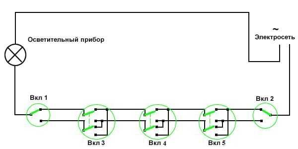 Scheme of organizing on/off lamp for 5 points.
 If you remove one of the cross switches from this circuit, you get a 4-point option, and if you add one cross switch to it, you get a 6-point option.
Two-key pass-through switch: connection diagram
In order to control the operation of two lamps from several points, there are two-key pass-through switches. They have six contacts. The main thing is to identify common contacts. They are determined according to the same principle as when searching for a common contact in single-key pass-through switches.
In a circuit that uses two two-key pass-through switches, significantly more wires are used.
The phase wire is supplied to the inputs of both switches, and the other inputs of the switches are connected to one of the ends of one and the other lamp. The free ends of the lamp are connected to the neutral conductor. The two outputs of one switch are connected to the two outputs of the second switch, and the other two outputs of that switch are connected to the other two outputs of the first switch.
 Wiring option for connecting two-key pass-through switches.
 If you want to control the operation of two lamps from three or four points, you will have to purchase two cross switches. Each pair of two-gang switch outputs is connected to one pair of one crossover switch. And so on, pair by pair, the outputs of the devices are connected to each other.
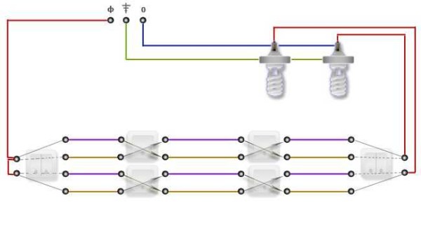 Controlling the operation of two lighting lamps from four points.
 If you look at it, there is nothing complicated, especially when using single-key pass-through switches. As for two-key pass-through switches, everything here is much more serious and costly, both in terms of wires and switches. To be more precise, this scheme is less practical, but more expensive.