DIY garage door remote control. Radio remote control system
The remote control of a VCR, TV, music center or satellite receiver can be used to turn off and on various household electrical appliances, including lighting.
Do-it-yourself remote control, the diagram of which is given in this article, will help us with this.
Description of the operation of the IR remote control system
For remote control The devices use the following mechanism. Press and hold an arbitrary button on the remote control for 1 second. The system does not respond to a short press (for example, when operating a music center).
In order to prevent the TV from responding to the control of devices, you must select unused buttons on the remote control or use the remote control from the device that is turned off at this time.
The schematic diagram of the remote control is shown in Figure 1. A special microcircuit DA1 amplifies and forms the electrical signal of the photodiode BL1 into electrical pulses. A comparator is built on radioelements DD1.1 and DD1.2, and a pulse generator is built on radioelements DD1.3, DD1.4.
The state of the control system (load on or off) is controlled by trigger DD2.1. If the direct output of this trigger is log 1, the generator will operate at a frequency of approximately 1 kHz. Pulses will appear at the emitters of transistors VT1 and VT2, which will go through capacitance C10 to the control pin of triac VS1. It will unlock at the beginning of each half-cycle of the mains voltage.
In the initial position, on pin 7 of the DA1 microcircuit there is log 1, capacitance C5 is charged through resistances R1, R2 and at the input C of the DD2.1 trigger, log 0. If IR radiation signals from the remote control are sent to the photodiode BL1, at pin 7 of the DA1 microcircuit there will be signals, and capacitance C5 will be discharged through diode VD1 and resistance R2.
When the potential at C5 drops to the lower level of the comparator (after 1 second or more), the comparator will switch and a signal will be sent to the input of the trigger DD2.1. The state of trigger DD2.1 will change. This is how devices switch from one state to another.

Microcircuits DD1 and DD2 can be used similar from the K564, K176 series. VD2 is a zener diode for a voltage of 8-9 volts and a current of more than 35 mA. Diodes VD3 and VD4 - KD102B or similar. Oxide containers - K50-35; C2, C4, C6, C7 - K10-17; C9, C10 - K73-16 or K73-17.
Setting up the IR remote control system
It consists of selecting resistance R2 of such a value that switching occurs in 1...2 s. If increasing the value of this resistance leads to the fact that capacitance C5 will not discharge to the threshold voltage, it is necessary to double capacitance C5 and make the adjustment again.
Capacitance C6 should be installed if the duration of the front of the pulse coming from the comparator to the trigger is excessively long and it switches unstably.
If the remote control used does not allow you to control the device without interfering with the TV, it is possible to assemble a homemade remote control, which is a generator of rectangular signals with a repetition frequency of 20...40 kHz, operating on an IR emitting diode. Variants of a similar remote control on the KR1006VI1 timer (
Who among the novice radio amateurs did not want to make some kind of device controlled by a radio channel? Surely many.
Let's look at how to assemble a simple radio-controlled relay based on a ready-made radio module.
I used a ready-made module as a transceiver. I bought it on AliExpress from this seller.
The kit consists of a remote control transmitter for 4 commands (key fob), as well as a receiver board. The receiver board is made in the form of a separate printed circuit board and does not have executive circuits. You need to assemble them yourself.
Here's the look.

The keychain is good quality, pleasant to the touch, and comes with a 12V (23A) battery.
The key fob has a built-in board on which a rather primitive circuit of the remote control transmitter is assembled using transistors and an SC2262 encoder ( complete analogue PT2262). I was confused by the fact that the marking on the chip is SC2264, although it is known from the datasheet that the decoder for PT2262 is PT2272. Immediately on the chip body, just below the main marking, SCT2262 is indicated. So think about what's what. Well, this is not surprising for China.

The transmitter operates in amplitude modulation (AM) mode at a frequency of 315 MHz.
The receiver is assembled on a small printed circuit board. The radio receiving path is made of two SMD transistors marked R25 - bipolar N-P-N transistors 2SC3356. A comparator is implemented on the operational amplifier LM358, and the decoder SC2272-M4 (aka PT2272-M4) is connected to its output.

How does the device work?
The essence of how this device works is as follows. When you press one of the remote control buttons A, B, C, D, a signal is transmitted. The receiver amplifies the signal, and a voltage of 5 volts appears at the outputs D0, D1, D2, D3 of the receiver board. The whole catch is that 5 volts will be output only as long as the corresponding button on the key fob is pressed. Once you release the button on the remote control, the voltage at the receiver output will disappear. Oops. In this case, it will not be possible to make a radio-controlled relay that would work when the button on the key fob is briefly pressed and turn off when pressed again.
This is due to the fact that there are different modifications of the PT2272 chip ( Chinese equivalent- SC2272). And for some reason they install PT2272-M4 in such modules, which do not have voltage fixation at the output.
What types of PT2272 microcircuit are there?
- PT2272-M4- 4 channels without fixation. At the output of the corresponding channel, +5V appears only while the button on the key fob is pressed. This is exactly the microcircuit that is used in the module I purchased.
- PT2272-L4- 4 dependent channels with fixation. If one output is turned on, the others are turned off. Not very convenient if you need to independently control different relays.
- PT2272-T4- 4 independent channels with fixation. Most best option to control multiple relays. Since they are independent, each can perform its function independently of the work of the others.
What can we do to make the relay work the way we need it?
There are several solutions here:
- We tear out the SC2272-M4 microcircuit and replace it with the same one, but with the index T4 (SC2272-T4). Now the outputs will work independently and latched. That is, it will be possible to turn on/off any of the 4 relays. The relay will turn on when a button is pressed, and turn off when the corresponding button is pressed again.
- We supplement the circuit with a trigger on K561TM2. Since the K561TM2 microcircuit consists of two triggers, you will need 2 microcircuits. Then it will be possible to control four relays.
- We use a microcontroller. Requires programming skills.
I didn’t find the PT2272-T4 chip on the radio market, and I found it inappropriate to order a whole batch of identical microcircuits from Ali. Therefore, to assemble a radio-controlled relay, I decided to use the second option with a trigger on the K561TM2.
The scheme is quite simple (the picture is clickable).

Here is the implementation on a breadboard.


On the breadboard, I quickly assembled an executive circuit for only one control channel. If you look at the diagram, you can see that they are the same. As a load, I attached a red LED through a 1 kOhm resistor to the relay contacts.
You probably noticed that I plugged a ready-made block with a relay into the breadboard. I pulled him out burglar alarm. The block turned out to be very convenient, since the relay itself, a pin connector and a protective diode were already soldered on the board (this is VD1-VD4 in the diagram).
Explanations for the diagram.
Receiving module.

The VT pin is the pin at which a voltage of 5 volts appears if a signal has been received from the transmitter. I connected an LED to it through a resistance of 300 Ohms. The resistor value can be from 270 to 560 Ohms. This is indicated in the datasheet for the chip.
When you press any button on the key fob, the LED that we connected to the VT pin of the receiver will flash briefly - this indicates that the signal has been received.
Terminals D0, D1, D2, D3; - these are the outputs of the PT2272-M4 decoder chip. We will take the received signal from them. A voltage of +5V appears at these outputs if a signal from the control panel (key fob) was received. It is to these pins that the executive circuits are connected. Buttons A, B, C, D on the remote control (key fob) correspond to outputs D0, D1, D2, D3.
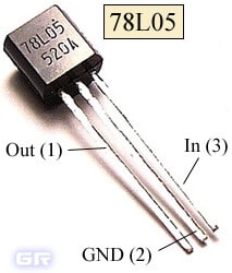
In the diagram, the receiving module and triggers are powered with a voltage of +5V from the 78L05 integrated stabilizer. The pinout of the 78L05 stabilizer is shown in the figure.
Buffer circuit on D flip-flop.
A frequency divider by two is assembled on the K561TM2 chip. Pulses from the receiver arrive at input C, and the D-flip-flop switches to another state until a second pulse from the receiver arrives at input C. It turns out very convenient. Since the relay is controlled from the trigger output, it will be turned on or off until the next pulse arrives.
Instead of the K561TM2 microcircuit, you can use K176TM2, K564TM2, 1KTM2 (in metal with gold plating) or imported analogues CD4013, HEF4013, HCF4013. Each of these chips consists of two D flip-flops. Their pinout is the same, but the housings may be different, as, for example, in 1KTM2.
Executive circuit.
Bipolar transistor VT1 is used as a power switch. I used KT817, but KT815 will do. It controls the electromagnetic relay K1 at 12V. To contacts electromagnetic relay K1.1 can connect any load. It could be an incandescent lamp, led strip, electric motor, lock electromagnet, etc.
Pinout of transistor KT817, KT815.

It should be taken into account that the power of the load connected to the contacts of the relay must be no less than the power for which the contacts of the relay itself are designed.
Diodes VD1-VD4 serve to protect transistors VT1-VT4 from self-induction voltage. At the moment the relay is turned off, a voltage arises in its winding, which is opposite in sign to that which was supplied to the relay winding from the transistor. As a result, the transistor may fail. And the diodes turn out to be open in relation to the self-induction voltage and “quench” it. Thus, they protect our transistors. Don't forget about them!
If you want to supplement the executive circuit with a relay activation indicator, then add an LED and a 1 kOhm resistor to the circuit. Here's the diagram.
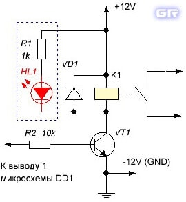
Now, when voltage is applied to the relay coil, the HL1 LED will turn on. This will indicate that the relay is turned on.
Instead of individual transistors in the circuit, you can use just one microcircuit with a minimum of wiring. Suitable microcircuit ULN2003A. Domestic analogue K1109KT22.
This chip contains 7 Darlington transistors. Conveniently, the pins of the inputs and outputs are located opposite each other, which facilitates the layout of the board, as well as the usual prototyping on a solderless breadboard.
It works quite simply. We apply a voltage of +5V to the IN1 input, the composite transistor opens, and the OUT1 output is connected to the power supply negative. Thus, supply voltage is supplied to the load. The load can be an electromagnetic relay, an electric motor, a circuit of LEDs, an electromagnet, etc.
In the datasheet, the manufacturer of the ULN2003A chip boasts that the load current of each output can reach 500 mA (0.5A), which is actually not small. Here, many of us will multiply 0.5A by 7 outputs and get a total current of 3.5 amperes. Yes, great! BUT. If the microcircuit can pump such a significant current through itself, then it will be possible to fry kebab on it...
In fact, if you use all the outputs and supply current to the load, you can squeeze out about ~80 - 100 mA per channel without harm to the microcircuit. Ops. Yes, there are no miracles.
Here is a diagram for connecting ULN2003A to the outputs of the K561TM2 trigger.

There is another widely used chip that can be used - this is the ULN2803A.

It already has 8 inputs/outputs. I tore it out from the board of a dead industrial controller and decided to experiment.
ULN2803A wiring diagram. To indicate that the relay is turned on, you can supplement the circuit with a circuit of LED HL1 and resistor R1.

This is how it looks on the breadboard.

By the way, ULN2003, ULN2803 microcircuits allow combining outputs to increase the maximum permissible output current. This may be required if the load draws more than 500 mA. The corresponding inputs are also combined.
Instead of an electromagnetic relay, a solid state relay (SSR) can be used in the circuit. S olid S tate R elay). In this case, the scheme can be significantly simplified. For example, if you use a solid-state relay CPC1035N, then there is no need to power the device from 12 volts. A 5-volt power supply will be sufficient to power the entire circuit. There is also no need for an integrated voltage stabilizer DA1 (78L05) and capacitors C3, C4.
This is how the CPC1035N solid-state relay is connected to the trigger on the K561TM2.
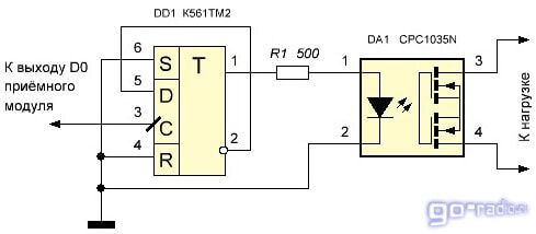
Despite its miniature size, the CPC1035N solid-state relay can switch alternating voltage from 0 to 350 V, with a load current of up to 100 mA. Sometimes this is enough to drive a low-power load.
You can also use domestic solid-state relays; for example, I experimented with K293KP17R.

I tore it off the security alarm board. In this relay, in addition to the solid-state relay itself, there is also a transistor optocoupler. I didn’t use it - I left the conclusions free. Here is the connection diagram.

The capabilities of the K293KP17R are quite good. It can switch direct voltage of negative and positive polarity within the range of -230...230 V at a load current of up to 100 mA. But it cannot work with alternating voltage. That is, constant voltage can be supplied to pins 8 - 9 as desired, without worrying about polarity. But you shouldn’t supply alternating voltage.
Operating range.
In order for the receiving module to reliably receive signals from the remote control transmitter, an antenna must be soldered to the ANT pin on the board. It is desirable that the antenna length be equal to a quarter of the transmitter wavelength (that is, λ/4). Since the key fob transmitter operates at a frequency of 315 MHz, according to the formula, the length of the antenna will be ~24 cm. Here is the calculation.

Where f - frequency (in Hz), therefore 315,000,000 Hz (315 Megahertz);
Speed of light WITH - 300,000,000 meters per second (m/s);
λ - wavelength in meters (m).
To find out at what frequency the remote control transmitter operates, open it and look for a filter on the printed circuit board for Surfactant(Surface acoustic waves). It usually indicates the frequency. In my case it is 315 MHz.

If necessary, you don’t have to solder the antenna, but the range of the device will be reduced.
As an antenna, you can use a telescopic antenna from some faulty radio or radio. It will be very cool.
The range at which the receiver stably receives the signal from the key fob is small. Empirically, I determined the distance to be 15 - 20 meters. With obstacles this distance decreases, but with direct visibility the range will be within 30 meters. Expect something more from this simple device stupid, its circuitry is very simple.
Encryption or “binding” of the remote control to the receiver.
Initially, the key fob and the receiving module are unencrypted. Sometimes they say that they are not “attached”.
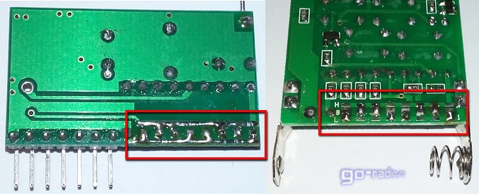
If you buy and use two sets of radio modules, the receiver will be triggered by different key fobs. The same will happen with the receiving module. Two receiving modules will be triggered by one key fob. To prevent this from happening, a fixed encoding is used. If you look closely, there are places on the key fob board and on the receiver board where you can solder jumpers.
![]()
Pins from 1 to 8 for a pair of encoder/decoder chips ( PT2262/PT2272) are used to set the code. If you look closely, on the control panel board next to pins 1 - 8 of the microcircuit there are tinned strips, and next to them are letters H And L. The letter H stands for High, that is high level.
If you use a soldering iron to place a jumper from the pin of the microcircuit to the strip marked H, then we will thereby supply a high voltage level of 5V to the microcircuit.
The letter L respectively means Low, that is, by placing a jumper from the pin of the microcircuit onto the strip with the letter L, we install low level at 0 volts at the pin of the microcircuit.
The neutral level is not indicated on the printed circuit board - N. This is when the pin of the microcircuit seems to “hang” in the air and is not connected to anything.
Thus, the fixed code is specified by 3 levels (H, L, N). Using 8 pins to set the code results in 3 8 = 6561 possible combinations! If we take into account that the four buttons on the remote control are also involved in generating the code, then there are even more possible combinations. As a result, accidental operation of the receiver by someone else’s remote control with a different encoding becomes unlikely.
There are no marks in the form of the letters L and H on the receiver board, but there is nothing complicated here, since the L strip is connected to the negative wire on the board. As a rule, the negative or common (GND) wire is made in the form of an extensive polygon and occupies a large area on the printed circuit board.
Strip H is connected to circuits with a voltage of 5 volts. I think it's clear.
I installed jumpers as follows. Now my receiver from another remote control will no longer work, it only recognizes “its” key fob. Naturally, the wiring must be the same for both the receiver and the transmitter.
By the way, I think you have already realized that if you need to control several receivers from one remote control, then simply solder on them the same coding combination as on the remote control.
It is worth noting that the fixed code is not difficult to crack, so I do not recommend using these transceiver modules in access devices.
The considered circuits are intended for remote control of loads via telephone wire line, mobile and radio communication channels, as well as control various devices using an infrared channel.
Device infrared control consists of two blocks - a transmitter and a receiver with a possible range of up to seven meters. The remote control circuit is built using a PIC12F629 microcontroller, the firmware of which you can download from the green arrow just above.

The basis of the IR transmitter circuit is the PIC12F629 microcontroller for its proper operation the RC5 protocol requires a stable carrier frequency of 36 kHz, so the design uses an external generator on radio components Q1, C1, C2.

The modulated IR signal from the transmitter is sent to the TSOP4836 receiving module and processed by the PIC12F629 in accordance with the firmware. Depending on the button pressed in the transmitter circuit, the desired channel in the receiver is activated. Relays switch the load on each channel. To flash microcontroller firmware, use .

It is quite easy to make an attachment for almost any radio call to control any household appliances. The modification allows you to remotely turn on and off a household appliance that has relay contacts inserted into its power circuit
On this page I have collected simple and easy to repeat schemes for remote control of loads on microcontrollers, for example lighting or any household appliances. You can find firmware and other additional files for projects here.
The considered circuits provide remote control of the load. Both designs have a programming function, which makes it possible by pressing a programmed button to turn on or off various loads at a distance
The schematic diagram of the transmitter is shown in Figure 1. SW1 is a module of eight DIP switches. It is installed on the board and allows you to set an individual code - an eight-bit binary number. The receiver must be set to exactly the same code, otherwise it will not respond to commands from this transmitter. Instead of a block of DIP switches, you can wire ordinary wire jumpers, but, again, the wiring must match the wiring of the jumpers on the receiving unit
The circuit is powered by a 5V power supply. The CD4017 digital microassembly is a typical counter divider by 10. The received signal from the sensor is sent to the microcircuit, in accordance with the signal at the outputs Q0-Q9, a high state is set; in our circuit example, a relay is connected to the Q1 output through a bipolar transistor T2. Almost any load can be connected to a high-voltage circuit - from a regular iron or microwave to a refrigerator or air conditioner

The illuminated Status LED indicates that the signal has been received and the relay has activated. Even any TV remote control can be used as a remote control. Appearance assembled device on a breadboard:

In this article we will talk about how to assemble IR load control with your own hands. The control circuit can control various loads connected to it: lights, fans, household appliances. IR control is carried out using any remote control, including television.
In the first scheme considered, the fan or cooler is controlled by a thermistor signal during a specified time interval. The amateur radio design is very simple, as it is assembled using only three bipolar transistors. Such control systems can be used in a variety of applications where fan cooling is required, for example cooling a computer motherboard, in powerful audio amplifiers and power supplies and similar devices that can overheat during operation.
DIY remote control of a chandelier
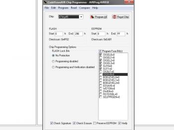
Once upon a time, I saw a chandelier in a store that was controlled by a remote control. And I wanted to control the lighting in the room while lying on the sofa, especially in the evening, when I didn’t want to get up and go to the switch. After some time, "GOOGLED" the Internet found a lot different schemes, but this one suited me best, because... there were also ATTINY45, and triacs, and other small things. I also liked in the author’s article that you can use energy-saving lamps. Having estimated and drawn the board, I assembled the device without changes. When flashing the controller, it turned out that the article did not indicate “FUSES”. After some thought, I sketched out the circuit in Proteus, calculated the placement of fuses, flashed the controller and the device started working immediately. I played around with the remote control and decided to check how it would work with energy-saving lamps.
Having changed incandescent lamps to energy-saving ones, the first time I turned them on, I successfully burned a couple of seven-storied lamps. Having thought a little, I reduced the resistors R9, R10 and replaced the semistors, I began to destroy the test, successfully destroyed a couple more, and stopped. Because I haven’t gotten the hang of writing programs for microcontrollers yet, so I decided to change the circuit a little.
Here's what happened: remove the one circled in red, add the blue one.
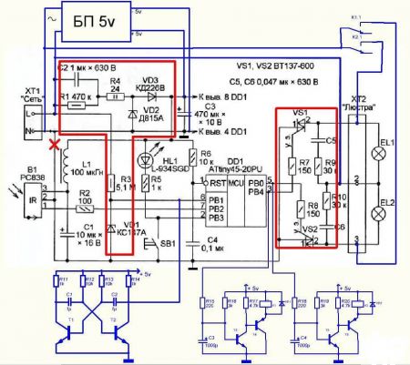
The need for network frequency pulses has not disappeared; without them, the circuit will not work (since, according to the firmware at the output, the controller controls triacs, and they, in turn, require pulse control). To galvanically isolate the controller from a 220-volt network, we add a simple multivibrator with two transistors, which will simulate network pulses with a multivibrator pulse frequency of about 70 Hz.
The output stages for turning on the relay are the same; we assemble them on two transistors.
About the elements used:
PSU – charger unit from mobile phone for 5 volts, you can use small-sized transformers UC30D-2 for a voltage of 6 or 9 volts, its dimensions are 32mm*27mm*15mm, where 15 mm is the height. Not forgetting about the diode bridge, capacitors and stabilizer 7805.
T1, T2 – any low-power npn soldered from the faulty one motherboard.
C1, C2 - at first I installed polar ones, but then I looked at SMD ones soldered from a faulty motherboard (there are a lot of them).
T3, T5 – VS817 (SMD, because less space occupy)
T4, T6 – BC807 (SMD, because they take up less space)
VD1, VD2 – KD521 (whichever ones were on hand)
K1, K2 - JZC-6F (5V) or HK4100 1Z (5V).
I tried different IR receivers: at 36 kHz and at 38 kHz - they work equally stably (TSOP4836 is better), but it is necessary to take into account the illumination of the receiver by lamps, it would be ideal to place glass in front of the receiver that is transparent in the IR region of the spectrum, or to place the receiver closer to the base of the chandelier .
The archive contains boards for the original circuit, for the JZC-6F relay, for the HK4100 1Z relay.
Fuses:
Photos of boards:

The control circuit along with the power supply easily fit into the base of the chandelier. I drilled three holes: for the LED, the button and the IR receiver, fixing them with hot glue (if you wish, you can not install the button, I set the resistor R5 to 2 kOhm so that there is less light at night).
It is worth adding that the scheme has been operating continuously for several months. Thank you for your attention…
Archive with boards, schematics, firmware and fuses.
Conveniently open garage doors without leaving your car. To achieve this opportunity, the gates are equipped with a remote control system. You can entrust this task to specialists, but with some skills you can organize remote control yourself. You can also install ready-made modules yourself.
When not to install automation
You should not make automation in unguarded garages or where there are frequent power outages. A de-energized gate will be easy for an intruder to open, so in this case it is necessary to install additional locks. But then you still have to get out of the car to open them, and remote control becomes meaningless.
On to the cons automatic gates This also applies to the fact that you will not open them if you forgot the remote control, the battery in the remote control is dead, or the antenna is broken. However, there are models that can be opened manually if the automation malfunctions.
Types of gates
For swing gates At least 4 photocells are required that will stop the movement of the valves if interference is detected between them. Two of them should be installed on the gate posts, and two should be installed on separately located posts at the maximum opening distance. To move them, two drives are needed.
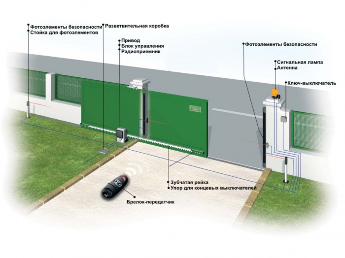
Sliding gates are safer in this regard. They require only one drive and two photocells. However, in practice this type is rarely found in private garages, since they are more difficult to maintain, the mechanism breaks more easily, they can warp or begin to jam, and they also take up a lot of space. In winter, you will need to regularly clean the rails to prevent icing. Swing systems are more durable and reliable.
For swing gates, when you press a button on the remote control, a signal is sent simultaneously to both drives, and the gate begins to open or close. Additionally, they make it possible to remove the lock so that if necessary (for example, in the absence of electricity), you can open the gate by hand.
Sliding control system garage doors simpler and, as a rule, done in one housing, which houses both the drive and the control unit.
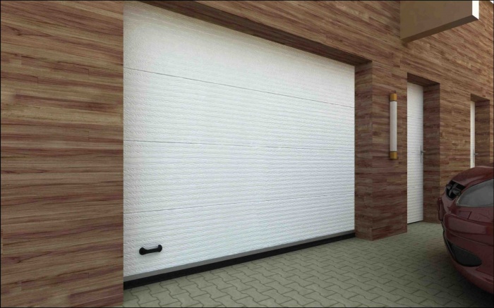
Sectional and roller shutter models are most often automated. It is for them that there are many drive options on sale; for swing and sliding ones there are fewer of them. Often such gates are already sold with a remote control system.
Remote control system design
Whatever the gate design, the automation includes the following elements:
- electric drive,
- control system,
- remote controller
- security system (sensors, photocells).
Sectional and roller garage doors have drives located on the ceiling. Such gates are already sold with a remote control system; all that remains is to connect them correctly.
![]()
The electric drive is the part that directly moves the sashes. This can be a chain or lever drive such as a jack. To move the shutters, install an electric motor with a power of 200-400 W, connect it through a transformer that reduces the voltage to 24 V or directly to a 220 V network. When purchasing a motor, pay attention to the materials from which it is made. Many Chinese models, for example, have plastic gears that cannot last long. All moving and rubbing parts must be metal.

Important! The gate must move easily, otherwise the drive will quickly break.
To connect automatic gate remote control, use a three-core cable with a length of no more than 50 m and a cross-section of at least 1.5 * 3 mm. Cable brands are suitable. It is laid along supports or in the ground in a polyethylene tube at a depth of at least 40, and preferably 70 cm. A cable is run from the control unit to the signal lamp and antenna.
To remotely control the gate, a radio key fob with two buttons is used. One is responsible for opening and closing, and the second is for lighting. You can also install a module that is controlled from a mobile phone, sometimes this is more convenient, since you always have your phone with you and it’s easy to forget the key fob. To open the gate without a key fob or phone, an unlocking system is provided. It will also help open the gate if it turns out to be de-energized.
How to make a remote control system with your own hands

The easiest way is to buy a ready-made system and install it. At the same time, if you know how to work with electronics, you can make a remote control for your garage door yourself. To do this, you need any inexpensive device with a remote control: a bell, a car door lock, a car alarm.
You can use remote control modules, for example MP325M.
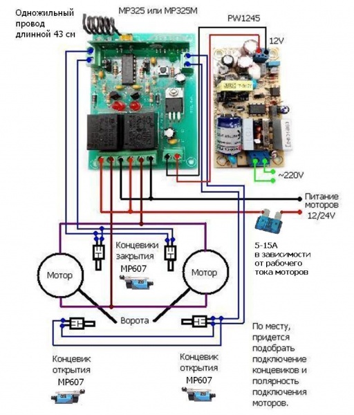
To supply power in this circuit, a PW1245 converter was used. You can also use a step-down stabilizer based on a single chip. However, the converter with its own separate power supply makes the entire system more reliable.
MP607 sensors were used as limit switches (gate status indicators, whether they are open or closed). This sensor has two groups of contacts. One of them is normally closed, the other is normally open. In this circuit, a normally open circuit was used for connection.
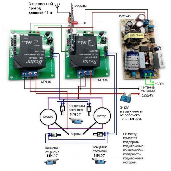
The MP325M module can be used in temperatures down to -15 degrees, so it is not suitable for use outdoors in winter. To operate the remote control at temperatures down to -40 degrees, you can replace it with the MP324M module with MP146 base units. The diagram is shown in the figure.
A single-core wire 43 cm long is an antenna. The length of the wire was selected based on the requirement that the gate open from the required distance. To select the length of the antenna to open from the distance required in your case, you first need to take a longer wire and select the desired length by gradually cutting it. It is best to place the antenna vertically above the gate. The antenna must not be bent, twisted, or placed in metal casings.
Connecting a finished control unit
If you purchased a ready-made control unit, you need to connect it, and you need to do it correctly. The signal lamp and antenna have only two or three wires: phase and neutral and sometimes ground. There are more wires on the block itself, there are wires for connection
- antennas,
- lamps,
- driving drives,
- photocells,
- programmer for configuration,
- in some cases - additional lighting; there is also a power cable.
The connection diagram of the control unit may be as shown in the figure.

- Contacts 1 and 2 are intended for connecting an external antenna.
- Contacts 3-6 are intended for connecting a keyboard from which system settings are configured.
- A beacon is connected to pins 7 8.
- To contacts 9-10 - one or two drives,
- To contacts 11-12 there are photocells.
- Contacts 13 and 14 are intended for connecting an additional lighting lamp.
- 15-17 are intended for connecting the power supply: 15 - zero, 16 - phase, 17 - ground.
The control unit is placed in a dust- and moisture-proof casing, the degree of protection of which must be at least IP 54 (complete protection from dust, protection from splashing water).
After a long power outage, the gate may not open. Then you will need to restart the system. Some of them have a battery, some have memory. Features of a specific model must be clarified with the seller.
Remote control of garage doors is very convenient, but it also has its disadvantages. Now you can install a remote control system on a gate of any design; for this you need to buy a ready-made system or, if you are knowledgeable in electronics, make it yourself.