What is the supply voltage for poe camera m12. What is a PoE adapter? Power over Ethernet
2015-01-28T17:00:00+0300 2015-01-28T17:30:00+0300 Vladimir Afanasyev
Power over Ethernet (PoE) is a technology that allows transmission to a remote device electrical energy along with data, via standard twisted pair on an Ethernet network. To transfer power, special network switches that support this technology are used.
About switches in general
First, let's figure out what network switches are and what types they come in.
Network switch aka switch (jarg switch from English switch - switch) is a device designed to connect several nodes of a computer network within one or more network segments.
All existing switches are different
- number of ports (2, 4, 8, 16, 24 and 48 ports, etc.)
- data transfer speed (100Mb/s, 1Gb/s and 10Gb/s, etc.)
- network layer support (network layer- layer1, layer2, layer3)
- PoE support and without it
Switches can also be divided into:
1.Unmanaged switches- These include almost all Layer 1 switches - these are simple stand-alone devices that manage data transmission independently and do not have manual control tools. Such switches are most widespread in “home” LANs and small businesses, the main advantage of which can be called low price And autonomous operation, without specialist intervention.
The disadvantages of unmanaged switches are the lack of configuration options and low internal performance. Therefore, in large enterprise networks, it is not wise to use unmanaged switches, since administering such a network is time-consuming, makes troubleshooting difficult, and imposes a number of significant limitations.
2.Managed switches Basically, Layer 2 and Layer 3 are more advanced devices that also operate in automatic mode, but in addition have built-in control and monitoring tools.
The main disadvantage of managed switches is their higher cost compared to Layer 1, which depends on the capabilities of the device itself and its performance.
We will not give any special comments on the number of ports and data transfer speed. Now, in a little more detail, who are these levels Level1 (Layer1), Level2 (Layer 2) and Level3 (Layer 3).
Layer 1. This includes all devices that operate at layer 1 of the OSI network model - the physical layer. Such devices include repeaters, hubs and other devices that do not work with data at all, but work with signals. These devices transmit information coming from one port and relay it to all ports at once. Such devices have not been produced for a long time, and it is quite difficult to find them on the market.
Layer 2. This includes all devices that operate at layer 2 of the OSI network model - the data link layer. Such devices include all unmanaged switches and some managed ones. Level 2 switches work with data not as a continuous flow of information (like Level 1 switches), but as individual pieces of information - frames. They are able to analyze received frames and work with MAC addresses of frame sender and receiver devices. Such switches “do not understand” the IP addresses of computers; for them, all devices are named in the form of MAC addresses. Layer 2 switches create switching tables that map the MAC addresses of encountered network devices to specific switch ports.
Layer 3. This includes all devices that operate at layer 3 of the OSI network model - the network layer. Which is responsible for the mutual conversion of hardware and network addresses (MAC/IP) - the ARP protocol, finding a path between two intermediate devices, establishing a logical connection between nodes. Such devices include all routers and some managed switches, as well as all devices that can work with various network protocols: IPv4, IPv6, IPX, IPsec, etc. It is more appropriate to classify Layer 3 switches as routers, since these devices are already fully capable of routing passing traffic between different networks. Layer 3 switches fully support all the features and standards of Layer 2 switches. Network devices can be accessed using IP addresses. A layer 3 switch supports the establishment of various connections: pptp, pppoe, vpn, etc.

Smart Switch Management
There may be several options.
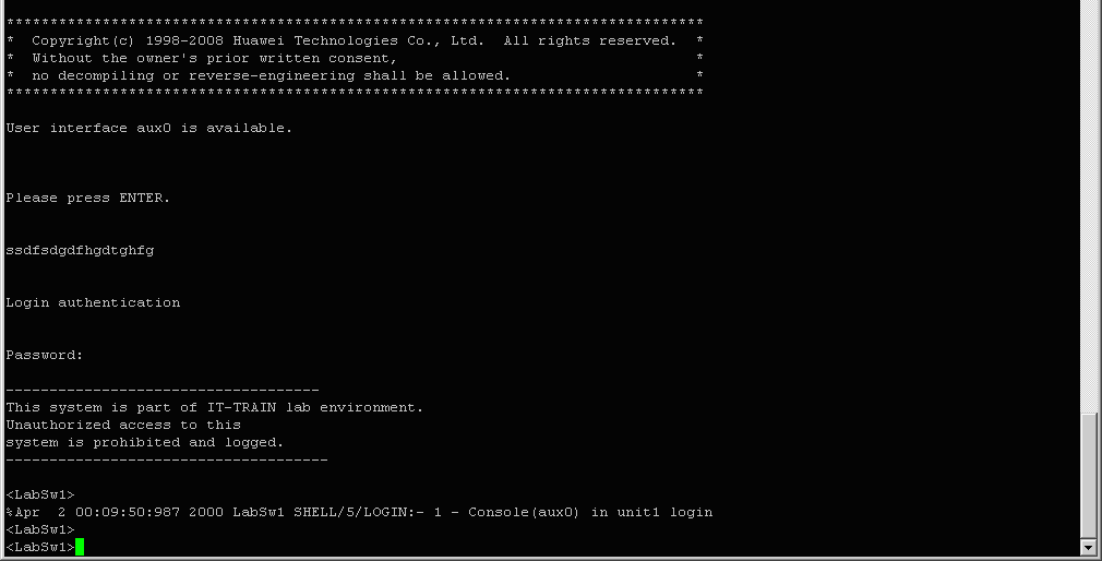
Telnet access to the console port of the switch. Configuration occurs through the command line of the switch. Telnet access is not secure.
SSH
SSH access to the managed switch is carried out using the secure SSH protocol, using various clients (putty, gSTP, etc.). Just as in the case of configuration, the configuration occurs through the command line of the switch.
Web interface
The setup is done via a WEB browser. In most cases, configuration via the Web interface does not allow you to take advantage of all the functions of network equipment, which are fully available only in command line mode.

Power-over-Ethernet
Now let's try to figure out why in these switches and so wide possibilities also PoE.
This technology is intended for IP telephony, wireless network access points, IP cameras and other devices to which it is undesirable or impossible to conduct separate electrical cable to supply power.
PoE technology does not affect the quality of data transmission. To implement it, the properties of the Ethernet physical layer are used.
Modern 100BASE-TX Ethernet cabling consists of four pairs, two of which are unused. Free pairs are used to supply power. PoE provides power supply over a standard twisted pair cable for remote devices such as wireless access points, IP phones, IP cameras, media converters, data readers, etc. Power is supplied over free twisted pairs 4-5 and 7-8, which are not used for data transfer.
802.3af PoE-A and PoE-B standards for 100 and 1000 Mbps networks. Pinout of 8-pin 8P 8C(RJ45) connector
Power sourcing equipment (PSE) differ in the way they connect power, while powered devices (splitters; powereddevice, PD) are universal. Powered devices are designed with the ability to receive power in any way, including when the polarity is reversed (for example, when a crossover cable is used).
It is important that the power supply only supplies power to the cable if the device being connected is a powered type device. Thus, equipment that does not support PoE technology and is accidentally connected to the power supply will not be damaged. The procedure for applying and disconnecting power to the cable consists of several stages.
The first step of connection detection is to determine whether the device connected at the opposite end of the cable is a powered device (PD). At this stage, the power supply unit (PSE) supplies the cable with a voltage of 2.8 to 10 V and determines the input impedance parameters of the connected device. For a powered device, this resistance ranges from 19 to 26.5 kOhm with a parallel connected capacitor with a capacity of 0 to 150 nF. Only after checking the compliance of the input resistance parameters for the powered device, the power supply device proceeds to the next stage, otherwise the power supply device again, after a time interval of at least 2 ms, tries to determine the connection.
After the first step of determining the connection, the power supply can further perform a classification step, determining the range of power consumed by the powered device in order to then control that power. Each powered device, depending on the declared power consumption, will be assigned a class from 0 to 4. The minimum power range is class 0. Class 4 is reserved by the standard for further development. Classification is performed by introducing a voltage from 14.5 to 20.5 V into the cable by the power supply device and measuring the current in the line.
After passing through the identification and classification stages, the power supply supplies the cable with a voltage of 48 V with a rising edge no faster than 400 ms. After applying full voltage to the powered device, the power supply monitors its operation in two ways:
1) if the powered device consumes less than 5 mA of current within 400 ms, then the power device removes power from the cable;
2) the power supply supplies the cable with a voltage of 1.9-5.0 V with a frequency of 500 Hz and calculates the input resistance; if this resistance is greater than 1980 kOhm for 400 ms, the power supply removes power from the cable. In addition, the power supply continuously monitors the overload current. If the powered device draws more than 400 mA current for 75 ms, the power supply will remove power from the cable. When the power supply detects that the powered device is disconnected from the cable or that the current consumption of the powered device is overloaded, the power supply is removed from the cable for a period of at least 500 ms.
There are currently two PoE standards in use: IEEE 802.3af PoE Standard and IEEE 802.3at-2009 Standard, also known as PoE Plus. Below is a table of two PoE standards and their classes for Ethernet cable type.
| Standard | PoEIEEE 802.3af | PoE Plus IEEE 802.3at |
|---|---|---|
| Cable Requirements | Category 3 (UTP CAT3) or higher | Type 1: Category 3 (UTP CAT3) or higher |
| Type 2: Category 5 (UTP CAT5) or higher | ||
| Current strength | 0.35 A | Type 1: 0.35 A |
| Type 2: 0.6 A | ||
| Injector output voltage | 44 - 57 V | Type 1: 44 - 57 V |
| Type 2: 50 - 57 V | ||
| Powered Device Input Voltage | 37 - 57 V | Type 1: 37 - 57 V |
| Type 2: 42.5 - 57 V | ||
| Maximum power consumption of the powered device | PoE class 0, 3: 12.95 W | Type 1: PoE Class 0, 3: 12.95 W |
| POE Class 1: 3.84 W | PoE Class 1: 3.84 W | |
| PoE Class 2: 6.49 W | PoE Class 2: 6.49 W | |
| PoE Class 4: not used | Type 2: PoE Class 4: |
|
| Supported Powered Devices | IP cameras, IP phones, access points | All PoE devices, outdoor PTZ cameras, |
| WiMAX access points, LED displays, some computers |
Despite all the advantages of using PoE technology standardized according to 802.3af, there are also disadvantages, for example:
- high additional cost devices with PoE function (802.3af);
- High power consumption of PoE switches compared to conventional ones.

Therefore they are issued alternative solutions, called "PassivePoE", in the form of an intermediate set of adapters that can only support electrical characteristics compliance with the 802.3af standard, (that is, the Passive PoE injector will transmit any voltage that is supplied by the power supply, not necessarily 48 V) but not protocol ones. Passive PoE is not fully compliant with the IEEE 802.3af standard.
Typically, a Passive PoE (PPoE) kit does not include a power supply because... It is assumed that the power supply supplied with the powered device is used. Maximum length cable when using a Passive PoE injector is significantly less than when using a PoE injector (30-60 meters, not 100 meters). Of course, this largely depends on the parameters of the standard power supply, the current consumed by the device and losses in the cable. To compensate for these losses over a long distance, it is enough to replace the standard power supply with a more powerful one, with a voltage of 12 to 48 volts.
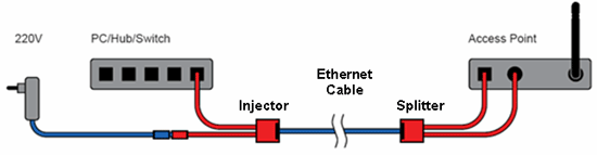
The passive PPoE-Light kit consists of two adapters: an Injector (INJECTOR) and a Splitter (SPLITTER). Passive PoE is effective for use in existing network infrastructure, allowing the use of PoE technology for devices that are not equipped with this function natively. The PPoE kit does not include any power supply unit (PSU), since it is assumed that in most cases you can use the standard PSU included with the device. PPoE provides power supply via a standard twisted pair cable for remote devices such as wireless access points, IP phones, IP cameras, etc. Power is supplied in the same way as in classic PoE over free twisted pairs 4-5 and 7-8, which are not used for data transfer.

Let's look at a small example of how to calculate the use of PoE in a combination of Yealink SIP-T48G phones supporting PoE (Power over Ethernet, 802.3af) Class 0 with a power consumption of 2.4-10.5W and Huawei Quidway S5700-28C-PWR-EI 24-port switches.
The S5700 PWR switches comply with IEEE 802.3af and 802.3at (PoE+) standards. And they can provide ports with a maximum load of up to 30W. In our case, the S5700-28C-PWR-EI has a power supply installed with a power of 500W and output for PoE369.6W. According to the 802.3af standard, we can power 24 ports from it with a load of 15.4 W per port, or according to the 802.3at standard, 12 ports with a load of 30 W.
Having carried out simple mathematical calculations we get:
10 phones at 10.5 W = 105 W in total, which is less than the maximum output for PoE369.6W.
It turns out that we can connect 24 Yealink SIP-T48G phones to the Huawei Quidway S5700-28C-PWR-EI switch via PoE. Or other equipment with 12 ports according to the 802.3at (PoE+) standard with a power of up to 30W, for example, HP t410AiO thin clients supporting the 802.3at (PoE+) standard with a power consumption of 24W 12 pieces.
Or combine various equipment, a video camera with Grandstream GXV3674_HD_VF with support for PoE IEEE802.3af, video intercom ROBIN SV 130 with support for PoE IEEE802.3af, etc. You can create quite a few different combinations of using PoE equipment.

Conclusion
There is quite a lot of controversy regarding the feasibility of PoE. The most common argument (in terms of power supply for IP phones) - we will supply for each workplace additional Pilot for 300 rub. and everything will work much cheaper. So, 300 rub. roughly we spend on each workplace (24 in total) = 7200 rubles. (about 110 USD)
Now let’s transfer this to switches and money:
- Huawei S2700-26TP-EI-AC - 24 ports without PoE - 441 USD
Huawei S2700-26TP-PWR-EI - 24 ports with PoE - 563 USD
The difference is 122 USD versus savings on “pilots” - 110 USD. Doubtful, isn't it?
Savings in terms of energy consumption in our realities are most likely a questionable thing. It would be more correct to position this technology as an additional convenience and a unique solution to the aesthetic issue with a bunch of wires under the table.
When choosing a switch for the office, we chose the model with PoE.
In this article, we will consider aspects of the application and purpose of PoE technology, the principles of supplying power to the line and the impact of implementation on the power supply network.
Adopted in July 2003, the IEEE 802.3af standard regulates the method of powering devices connected to an Ethernet network, which involves the use of a data cable.
Wikipedia defines PoE in the following way:
Power over Ethernet, or PoE, is a technology that allows you to transmit electrical energy along with data to a remote device via a standard twisted pair cable in an Ethernet network. This technology is intended for IP telephony, wireless network access points, Web cameras, network hubs and other devices to which it is undesirable or impossible to install a separate electrical cable.
From there it immediately becomes clear for what purpose this technology was invented - who wants to drag the power cable to a webcam or VoIP device, thereby already increasing the cable management of an office or home.
True, you need to be careful when rushing to implement PoE everywhere, because... this implementation requires a review of power supply and cooling issues (naturally we're talking about on industrial implementation)
If you do not take into account the increased demands for power supply and cooling capacity, you must be prepared for unexpected outages and disruptions in the operation of equipment. Since PoE is commonly used in communication and access control systems, negative effect from such outages is especially noticeable.
How is power supplied to the line?
The following methods are available to supply power to an Ethernet network:- switch with voltage supply to the line;
- “power injector” installed between the switch and the cross-connect;
- crossover with voltage supply to the line;
- “power injector” for one line (the latter provides power to PoE-compatible devices in networks that do not have such support)
PoE technology does not affect the quality of data transmission. To implement it, the properties of the Ethernet physical layer are used:A) The use of high-frequency transformers at both ends of the line with a central tap from the windings. The constant supply voltage is supplied to the central taps of the secondary windings of these transformers, and is also removed from the central taps on the receiving side. The use of central taps of signal transformers allows, without mutual influence, to transmit both high-frequency data and constant supply voltage over one pair of wires.
B) Using free pairs to connect power. Modern 100Base-TX Ethernet cabling consists of four pairs, two of which are unused.
Accordingly, there are two options for power supply to the PSE device:
- A - to the twisted pairs through which data flows
- B - to unused pairs in the cable
PSE devices (injectors) differ depending on options A or B, while splitters, that is, PD devices, are universal. The PD device must be able to accept power in any variant, including when the polarity changes (for example, when a computer-to-computer crossover cable is used). It is important that the PSE device only supplies power to the cable if the connected device is a PD type device. This way, non-PoE equipment accidentally connected to the PSE device will not be damaged. The procedure for applying and disconnecting power to the cable consists of several stages.
Extremely permissible level power is about 15-16 W per port at a current of 350 mA and a voltage of 48 V; based on these limitations, a list of devices is emerging that can be powered using this technology.
A typical IP phone consumes up to 5 watts of power; a video-enabled IP phone, like an RFID tag reader or fixed CCTV camera, consumes 10-12 watts; a wireless access point, card reader, or electromechanical lock- from 8 to 12 W.
The current version of the PoE+ standard (IEEE 802.3at) will allow connecting devices with power consumption up to 30 W when transmitting data on two pairs (10BaseT and 100BaseTX) and equipment with a power consumption of up to 60 W when transmitting on all four pairs (for Gigabit Ethernet 1000BaseT) . Thus, Wireless Mesh Network access points with a power of up to 50 W, controlled video surveillance cameras with power consumption of up to 20 W and other sufficiently powerful devices will be able to receive power over a single wire.
What should you pay attention to when implementing PoE in a corporate network?
Let's say our office has 50 machines. There are two 48-port switches and an “injector” for supplying voltage to PoE-enabled devices. And let’s assume that our devices will require no more than 7W of power.
Without the use of PoE technology, the power consumption of small office switching equipment will not exceed 90 W. To support such a load, a 500 W/750 VA UPS is sufficient.
However, if we power all telecommunications equipment, web cameras and others from the UPS optional equipment, then we will have to take into account the increased load (for a small office with 50 active devices it will increase by about 6 times) on the UPS, which may entail replacing the UPS with a more powerful analogue.
You may also have to perform heat dissipation calculations, because The new UPS will generate more heat in battery charging mode.
Today we will get acquainted with a very simple network technology that can greatly facilitate the installation of network equipment in an office or enterprise. POE (Power Over Ethernet) technology, which allows you to power network equipment via a network cable, eliminating the need for users to install electrical outlets where it is inconvenient and use bulky power supplies.
Benefits of POE technology
When installing a Wi-Fi access point, network camera or router in the office, you are forced to consider where the nearest electrical outlet is installed to connect the device's power supply to it. This often limits your options, and if you want to achieve best level Wi-Fi signal, you want to place the access point under the ceiling, you may be faced with the problem of choosing - either install electrical wiring and install an outlet under the ceiling, or install the access point in a more convenient place, sacrificing signal quality.
And if you are installing network equipment in hard-to-reach places (for example, under the roof of a hangar, in the attic, etc.), then the cost of electrical wiring and installation of sockets may seem simply exorbitant. To solve this problem, a new IEEE 802.3AF standard was created, which allows not only data to be transmitted over Ethernet networks, but also electricity. Thus, the purpose of this standard is to provide power to peripheral devices using signal lines. If any of you remember about data transmission over power supply networks, then IEEE 802.3AF is exactly the opposite. The IEEE 802.3AF standard implies the use of existing signal lines, which means you can use any twisted pair standards - 10Base-T, 100Base-TX, 100Base-T. Existing cable systems of the third and fifth categories are sufficient for the operation of the devices. Unlike power supply networks, where power is distributed to all electrical receivers, in the case of the POE standard, power is supplied individually to each device.
Voltage. All computer equipment Powered by DC, so there is no point in transmitting 220V via RJ45 alternating current. The 802.3af standard involves DC transmission over twisted pair cables. voltage from 44 V to 57 V (nominal - 48 V). The choice of this particular voltage value is justified by the fact that it can be supplied to twisted pairs of structured wiring of any category without restrictions on duration. It is also important that in an office environment the specified voltage is not dangerous to the user’s life. Maximum D.C., which can flow through one conductor of a twisted pair of linear and corded SCS cables, regardless of its form and category, is limited by current standards within 175 mA. To double this value without breaking technical specifications manufacturer, to transmit power current in one direction, both conductors of the pair are simultaneously used, which are connected in parallel to the corresponding pole of the source and consumer. Thus, a current of up to 350 mA. In total, the power of a POE device can reach 16 W, more than enough!
Distance, to which voltage can be transmitted in the IEEE 802.3af standard, is 100 meters.
Thanks to automatic resistance measurement, network devices determine, even before applying voltage, what voltage the receiver will need and whether the receiver supports POE technology at all. This prevents damage to devices that do not support IEEE 802.3af.
Now network devices are just beginning to acquire support for IEEE 802.3af, and three types of POE devices are used to power equipment over twisted pair cables.
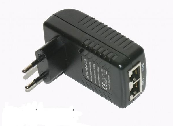
POE injector. A device that transmits electrical power to signal cables. A POE injector can be built into network equipment, for example, a router, or it can be a separate device. In the latter case, it is connected to the RJ45 cable section and to electrical outlet. It turns out that the POE injector has only data at the input, and data and electrical voltage at the output.
POE splitter. A device that is the opposite of the injector for its intended purpose. The splitter connects to a POE network, in which electrical power is also transmitted through the signal wire, and separates the electrical component from it separately, and the signal component separately. That is, it has a standard RJ45 network port at the input, and an RJ45 and power connector at the output. The splitter is used to power devices in IEEE 802.3af networks that do not support this standard. That is, to power an old router or network camera from Ethernet.

Network device, powered by POE. Actually, it could be a network camera, router, network hard drive, switch, etc. that supports POE. As a rule, such devices are supplied without power supplies, which results in savings on the purchase and delivery of equipment.
In general, the scheme for constructing a POE network looks like this:

The diagram shows a conventional switch from which signal lines extend of blue color. Using two Level One POI-2000 POI injectors, electrical power is added to the signal line. In the upper part of the diagram, a network camera that does not support the IEEE 802.3af interface is powered via a POE network. Therefore, a POS-1000 splitter is installed in front of it. At the bottom of the diagram, an access point that supports POE is connected to the POE network, so it does not need an additional splitter.
Well, it's time to get to know POE devices better.
Level One WAP-0009 access point and Level One POI-2000 POE injector
Let's look at the operation of POE equipment using the Level One WAP-0009 access point as an example. This is a SOHO-class access point for use in the home or small office. Level One WAP-0009 supports IEEE 802.11b/g wireless standards and can provide Wi-Fi connection speeds of up to 54 Mbps.
Characteristics of Level One WAP-0009
up to 54 Mbit/s (6/9/12/18/24/36/48/54) in 802.11g networks
up to 11 Mbit/s (1/2/5.5/11) in 802.11b networks
-
WEP 64/128-bit
WPA2 (AES Encryption)
Control by MAC address
IEEE 802.11b/g standard
Frequency 2.400 - 2.4835 GHz
Data transfer rate:
Modulation CCK 11/5.5 Mbps, DQPSK@2Mbps, DBPSK@1Mbps
Detachable antenna
Transmitter signal 18 dB
One 10/100 Mbps Auto-MDIX RJ45 network port supporting POE function
Operating modes:
Dimensions 127x96x30 mm
This access point is also interesting because it supports WPA2 and WEP 128-bit protocols, as well as Bridge operating mode and MAC address filtering. Interestingly, Level One WAP-0009 comes without a power supply, but it can be purchased separately if you do not want to use a PoE network.

The WAP-0009 access point has a silver body, made in a design characteristic of the entire line of Level One network equipment. On the front side there are PWR, WLAN and LAN indicators.

WITH reverse side the case has a power socket installed - if your network does not support PoE, you can choose a power supply for the access point on the market. The access point has only one RJ45 network port, as you can see, it is exactly the same as on other network equipment. PoE technology does not make changes to the port design. To the left of the antenna in the recess there is a "Reset" button.
To operate the WAP-0009 network access point, we need a Level One POI-2000 PoE injector.
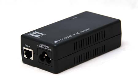
This is a low-level device that does not require driver installation. It is connected to the network cable and to a 110-220 V power outlet. At the input, the injector has regular Ethernet, and at the output there is a signal integrated with power.
Conclusion
PoE technology was conceived precisely to make it possible to save money when laying networks in homes and offices. But as often happens, the price of new items turns out to be higher than expected. And while the market is only just filling up with equipment that supports PoE, situations are quite possible when sellers will ask for additional money for PoE support, despite the fact that they save on power supplies. Don't be fooled - Power over Ethernet will be as common as powering rotary phones from a telephone jack, and over time Ethernet networks will be upgraded with this feature. But there are no inhibitory factors for her - full compatibility networks with older devices, automatic power adjustment, safe voltage and low cost.
If you are just planning to install local network in your apartment, house or office, then start your search for network equipment with devices that support PoE.
We thank the company "SVEGA Computer", official distributor Level One in Russia for the equipment provided.
LIKE OFF
5/03.2007
Today, I will tell you how you can connect an IP camera via twisted pair cable along with power to a computer, switch or recorder at a distance of no more than 100 meters.
Since we need only 4 wires to transmit data over twisted pair cable at a speed of 100 MB, we will use the remaining 4 for power supply, 2 each for plus and minus.
To connect we need:
- Crimping Tools
- RJ45 plug
- twisted pair
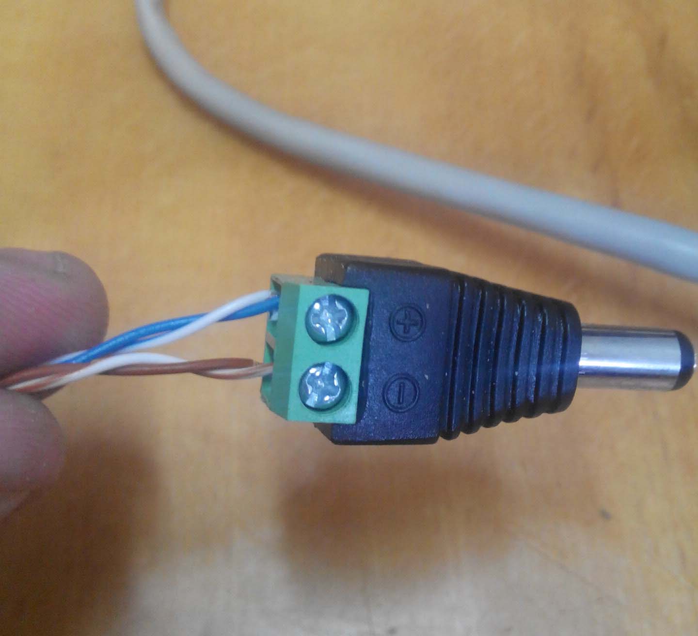
- Plug for connecting power to a video camera 2.1 mm x 5.5 mm
- power unit
- The video camera itself.
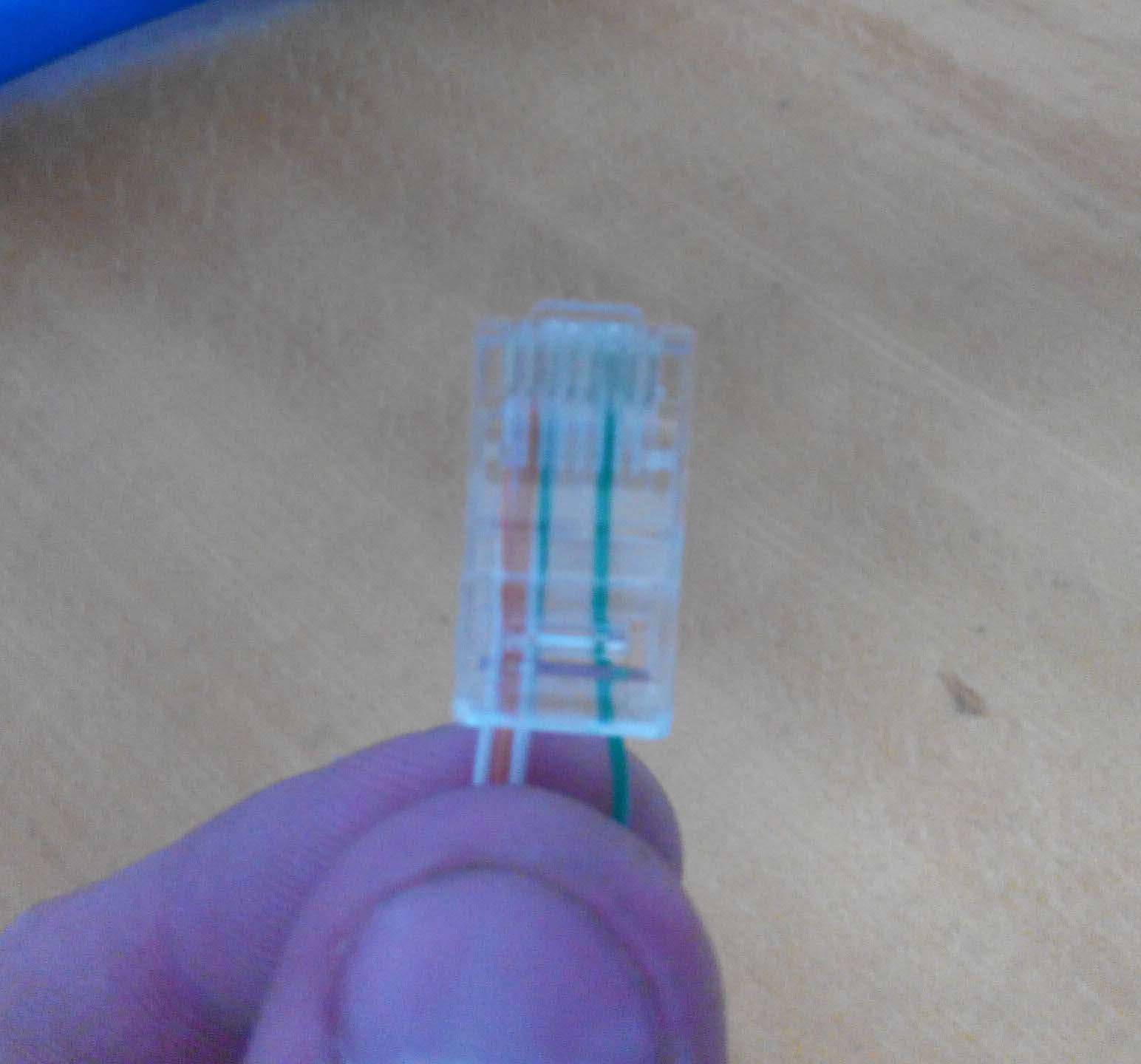
To connect RJ45 I use a direct crimp circuit for 4 wires of an orange and green pair.

The brown and blue pair are used to connect the power. I always use the blue pair as a plus, the brown pair as a minus.
First, we remove the insulation from the twisted pair, 7-10 centimeters is enough. We separate the pairs, green and orange in one direction, blue and brown in the other.


Now comes the hardest part, putting on RJ45 according to the scheme, namely:
orange-white – 1 pin,
orange – 2 pins,
green-white – 3 pins,
green – 6 pins.
Exactly with 6 pins at first most problems, but with practice this procedure goes very quickly.
Having crimped the twisted pair, we proceed to connecting the power. For this purpose connectors like 2.1 mm x 5.5 mm. The plus and minus terminals are already marked on them; we simply clear the insulation from the wire there, and clamp the blue pair with bolts, respectively, to the plus, and the brown pair to the minus.

A little about the power supply and its power. According to the passport, external surveillance cameras consume a maximum of 500 milliamps, which in practice is not entirely true. I calculate the power of the power supply with a reserve, and allocate about 1 ampere to one camera. Since the cable length can be 100 meters, there are always some losses, plus voltage is also lost at the connectors. At night, the camera works with infrared illumination, which also increases the load. In the example, I connect the camera to a 12V, 5 amp power supply. Very good blocks power supply, very reliable, and at the same time the load is supported by more than the declared 5 amperes. According to my measurements, the output was 6.5 amperes, which is not bad.


By connecting the wires to the power supply, and RJ45 to the network, testing the camera. Before connecting the camera, there is a break in network cable you can check it, which I reviewed in one of the articles.
With the help of which PCs can be connected into a network, one remarkable feature is hidden. The fact is that not only a digital data stream can be transmitted through them, but also power supply. To do this, it must be involved additional devices— PoE adapters. At the same time, there is a large number of their varieties and methods of connecting these devices to the network. What are the specifics of operation of such equipment?
Device Basics
A PoE adapter is a device that uses the capabilities of PoE technology, which allows you to transmit power through a regular twisted pair cable to the required device. In this case, the ability of the Ethernet cable to communicate is not lost, and the network remains fully functional.
The abbreviation PoE stands for Power over Ethernet. That is, “power via the Ethernet standard.” A PoE adapter is sometimes called an “injector” - but the second type of device is still more correctly considered a variation of the first. Let's study the specifics of using the device in question in the context of using the capabilities of PoE technology.
More about the technology
Power over Ethernet technology allows you to provide power to a variety of types of devices: Wi-Fi routers, cameras, drives. The main advantage of this technology is that it involves the use of a single set of wires - both for transmitting digital signals and for supplying electricity.
As a result, when installing networks, there is no need to lay wires for sockets, or to install the necessary additional electrical equipment. In some cases, installation of power cables may be complicated by less than optimal physical placement of network components. For example, it happens that a Wi-Fi adapter provides the best signal at a point in the building where it is difficult to supply electricity. The same can be said about cameras: sometimes there may be a need to monitor areas that are difficult to provide with power.
PoE technology allows you to organize the connection of devices to sockets, which can, as we noted above, simultaneously connect the device to the network and supply power to it. This approach can be used in case of modernization of the current network infrastructure. It is quite possible to supply power to existing sockets.
Benefits of technology
So, if we summarize the key advantages of the technology in question, they can form the following list:
The same cable can be used for both power supply and digital data exchange;
Possible economic benefits associated with no need to install power cables and other necessary equipment;
Achieved high level infrastructure of the appropriate type, thanks to the presence of standards that provide the necessary protection of components from power surges;
It is possible to modernize the current network infrastructure, organize communications in areas that were previously inaccessible for installation due to the need to lay electrical cables;
It is possible to organize remote control over devices via

Let us now study the main standards on the basis of which PoE networks operate.
Standards
The main protocol used in organizing the corresponding infrastructure is IEEE 802.3af. It involves the inclusion of 2 types of devices in the network - power sources and consumers. They can be, as we noted above, Wi-Fi routers, network drives. Cameras work great in such systems. Among the well-known manufacturing brands that produce devices with which the PoE adapter can interact is Axis.
Devices of the first type - sources - can be located at the initial section of the network or between the device supplying power and the consumer. The standard in question allows power supply over unshielded twisted pair cables of various classes - in particular, it supports 5, 5e and 6 at a voltage of 48 V and power consumption within 15 W. At the same time, there is no impact on the quality of digital data transmission via cable and no significant modernization of the current network infrastructure is expected.
Voltage supply methods
A network operating based on the Power over Ethernet standard can be supplied with electricity through two circuits.
Firstly, you can use signal transformers classified as high-frequency at the end sections of lines. The supply voltage will be supplied to their central taps. Similarly, from them, but on the receiving side, the voltage will be removed. This technology allows you to use the same pair of wires for both broadcasting high-frequency signals and transmitting electricity.
Secondly, you can use the free pairs present in the cable of the appropriate type to transmit power. How is this possible? The fact is that in practice, 2 of the 4 pairs that are in an Ethernet cable are often not used. Of course, if we are talking about their compliance with 100 Base TX technology.
The noted specifics of organizing the operation of a network in the PoE format suggest that the features of using injectors will depend on which method - the first or second - the voltage is transmitted. Thus, the capabilities of the noted 802.3af standard allow the transmission of electricity to pairs in bundles of 1.2 or, for example, 4.5 cables. In turn, the injectors can be fully compatible with 100 Base TX technology. However, if we are talking about splitters, then they must work with any of the power transmission schemes noted above, even if the polarity of the connection is changed.
Types of PoE equipment
There are several classes of equipment capable of operating in power transmission mode over twisted pair cable. A PoE adapter is one of them (the corresponding devices have a large number of varieties - we will study their specifics). Along with it, there are also PoE switches, as well as consuming devices. In many cases they can be integrated into one system. Let us study the specifics of the operation of each of the noted types of equipment in more detail.
Consuming devices
Consuming devices are, in fact, the same network devices that are supplied with power over twisted pair cables. Their important characteristic is input impedance. The corresponding indicator is usually determined in the range of 19-26.5 kOhm. As a rule, in the structure of the system to which consuming devices are connected there is also a capacitor.
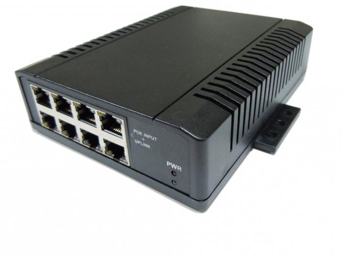
Switches
The PoE switch is designed to ensure the functioning of the network in terms of recognizing the correctness of cable connections to access points. Networks of the corresponding type operate based on the 802.3af protocols, which we mentioned above, as well as 802.3at. They allow you to ensure the interaction of various devices in conditions of possible power surges. If the PoE switch is not used, then there is a possibility that due to random fluctuations in the current in the twisted pair, the consuming device will fail.

Adapters
Devices of the type in question, as we noted above, are classified into additional varieties. So, a PoE adapter can be a power supply. Its structure contains a power supply, as well as a conjugation element, which can be equipped and in this case look like a small box or be a regular wire. PoE, in fact, is sometimes called an injector. On Russian market There are a large number of solutions of this type. For example, the PoE adapter TP Link 150S is popular. The most important technical specifications device of the appropriate type - stabilized voltage. The optimal indicator is considered to be 48 V, if we talk about the marked device model from TP Link.
Another type of PoE adapter is the receiving one. It, however, is also used to provide power to devices using twisted pair, but only those that do not belong to the consuming category. In order for such equipment to function, it is desirable that its power does not exceed 24 W. It can be noted that within the class of devices under consideration, devices belonging to the category of splitters are distinguished. In fact, they can also be classified as consuming devices.
If we talk about PoE adapters, which are splitters, they are designed to work with another type of device - PoE-Switch. That is, their main function is to separate network data into separate streams for the purpose of subsequent transmission to devices that do not belong to the category of consuming devices. Splitters are responsible for converting the voltage supplied to them to levels that are optimal for the final equipment - for example, these can be 5, 12 or 48 V.

In turn, splitters are also classified into two types - active and passive. As for the former, they can function with both switches and power adapters. Such devices include, for example, a splitter like DWL-P50 from D-Link. A PoE adapter, classified as a device of this type, can also be passive. They can only work with injectors. Moreover, as experts note, they are often sold together with them in a single set.
Nuances of using adapters
If adapters using Power over Ethernet technology are properly connected, problems with organizing the network should not arise. But some difficulties, due to the specifics of the standards used in such systems, may still arise. For example, PoE-Switch can determine that the active source is not a consuming device, and the network may temporarily lose power due to the fact that a passive splitter is enabled in the system. It is necessary, in turn, to replace it with an active one. Other possible problem— power off when trying to connect a consuming device to the switch. You can solve this by installing an additional device - a PoE converter.
An interesting fact is that from the point of view of the costs of the enterprise in which the network is being laid, with a small number of consuming devices it is more profitable to use passive devices, and with a large number - active ones. Some IT specialists believe that after the number of access points exceeds 3, active adapters can be used.

Optimal cable type
Power over Internet technology thus involves the use of twisted pair cables. But, as you know, they happen different types- for example, with 2 and 4 pairs. Which one is best suited for installing the corresponding type of network? As experts note, the system will retain its functionality when using any type of cable. But if we are talking about a heavy load on the switch - for example, if all its available ports are used, then a cable with 4 pairs is the best option.