Valve for hot water supply. Balancing valves - protecting hot water supply from legionella growth
For many novice plumbers there are many mysteries and mysteries. In this article I will try to explain how it will work with a servo drive of three different models. We will look at the operating logic and electrical connection diagram.
Option 1: Price from 6300 to 9200 rubles. There may be variants of articles.
Option 2: The price is about 2500-5000 rubles if you try to find it on a Chinese website and order it from China.
Option 3. An expensive option, but there are a lot of options. The price can be about 15-20 thousand rubles.
Connection diagram of a three-way valve with a servomotor for domestic hot water supply

The valve can be installed both on the supply line (supply) and on the return line of the pipeline (return).
Many will ask the question:- Where is it better? For supply or return?
In terms of DHW functionality, this is not important. But there are some nuances why it is necessary to put it on supply or return.
Nuances between supply and return:
Anyone Do any of you know why it is necessary to install a hydraulic accumulator on the return line of the pump? Or does he think it can be placed anywhere? Do you know why the pump is installed on supply or return? Answer: This is because the distribution of pressure in the air changes depending on where these elements are located. different points pipeline. And in some cases, the reason again becomes the convenience of filling and draining coolant in the heating system. It also helps to avoid airing and much more.
Why Does the boiler equipment manual recommend keeping the pressure at least 1.5 Bar? Because the pressure in the boiler heat exchanger cannot be reduced! A decrease in pressure leads to cavitation of the coolant in the heat exchanger. It also leads to early boiling of the coolant. And all this leads not only to a decrease in boiler power, but also to the deposition of scale in the heat exchangers, which leads to scale deposition and overgrowth of the heat exchangers. Which in turn will lead to a short service life of the boiler equipment.
Do you think, if the pressure gauge shows 1.5 Bar, this means that pressure less than 1.5 Bar cannot be present in the system at the same height. Where is the pressure gauge? Answer: This can happen and more often it happens to owners who independently figure out where the pump and hydraulic accumulator will be located. And they don’t understand how the pressure will be distributed after that.
Also how does a hydraulic accumulator affect pressure distribution: http://santeh-baza.ru/viewtopic.php?f=2&t=93
Why do you need a three-way valve for domestic hot water?
The main task of a three-way valve for domestic hot water is to redirect the movement of coolant from the heating system towards the Boiler indirect heating(another heat exchanger) and back in automatic mode.
As soon as the command comes to heat the indirect heating boiler, you need to redirect the coolant towards the BKN coil. The heating signal is generated by a special relay, which is located at the BKN (Indirect Heating Boiler). That is, the BKN has a built-in electric thermal relay, which provides a switching contact.
What does a three-way valve for domestic hot water look like?
Electrical diagram of the valve operation for the DHW boiler Thermona?

Electrical diagram with boiler and boiler

The servo drive has three contacts, one common. If you give a voltage of 220 Volts to two contacts (direction 1 + common), there will be one position. For another position, you need to give a voltage of 220 Volts to the other contact (Direction 2 + common). Phase and neutral of a 220 Volt network is not important.
Option 3. Most difficult option, which requires more detailed study. Has a variety of functionalities.

If you have a more efficient heating + hot water system with higher costs. It is not possible to use valves of options 1 and 2, since they have low capacity!
This device consists of two parts:
1. Rotary mixing valve (diameter optional)
Servo drive ESBE

Servo drive model: ESBE ARA641 for 220 Volts. 30 seconds. Article number 12101100
Drive characteristics:
1. Rotate 90 degrees. There is a degree adjustment setting. You can do a little more or move it a little to the side.
2. 3 point control. That is, 3 220 Volt contacts for control: Terminal 1, terminal 2 and common terminal.
3. The time it takes for the drive to rotate 90 degrees depends on the model. Model ARA641 30 sec.
4. Wire cable 1.5 meters.
5. Torque force: 6 Nm.
Servo drive electrical circuit: ESBE ARA641
This device has three conductors: Blue, brown and black.
Blue– common conductor, usually Zero is connected to it
Brown and black These are position 1 and 2 conductors.
When there is a voltage of 220 Volts on the blue and black drives, the drive rotates 90 degrees in one direction.
When there is a voltage of 220 Volts on the blue and brown drives, the drive turns 90 degrees in the other direction.
Such servos have a button to disable the direction of movement. That is, you can force the valve to the desired position during repairs or tests.

Please note that the larger the number, the more torque may be required.
In the ESBE catalog You can choose other valves and servos!
For example,
1. Select not three-point (three-contact) control, but two-point control. That is, a constant voltage goes to one contact, and you simply give or take away voltage to the second contact.
2. The rotation angle can be more than 90 degrees. For example, 180 degrees.
3. The closing time is not 30 seconds, but much longer. For example, you may need to smoothly transition up to 1200 seconds.
4. Take a drive with a different torque force.
5. Drive 24 or 220 volts.
6. Can be selected not only for switching, but also for receiving desired temperature mixing.
Download ESBE catalog for selecting valve and actuator: esbekatal.pdf
If someone has a two-point signal from an indirect heating boiler or from some thermostat that has only a two-point contact, then an electromagnetic switching relay can be used.

This model should be looked for in specialized electrical and electronics stores.
Model: ABB CR-P230AC2. 220 volts are supplied to pins 1 and 2. The load of the switching contacts must not exceed 8 amperes. 8 A x 220 Volts = 1700 W. Can withstand equipment up to 1700 W. Does not apply to pumps and incandescent lamps since the first start-up requires high currents.

In order to connect it to the wires, a special connector is used:
ABB CR-PLSx (logical) socket for CR-P relay

It should look like this:

That's all. Ask questions! Did you understand everything? Maybe something is missing?
| Comments(+) [ Read / Add ] |
A series of video tutorials on a private home
Part 1. Where to drill a well?
Part 2. Construction of a water well
Part 3. Laying a pipeline from the well to the house
Part 4. Automatic water supply
Water supply
Water supply for a private home. Operating principle. Connection diagram
Self-priming surface pumps. Operating principle. Connection diagram
Self-priming pump calculation
Calculation of diameters from central water supply
Water supply pumping station
How to choose a pump for a well?
Setting up the pressure switch
Pressure switch electrical diagram
Operating principle of a hydraulic accumulator
Sewage slope per 1 meter SNIP
Heating schemes
Hydraulic calculation of a two-pipe heating system
Hydraulic calculation of a two-pipe associated heating system Tichelman loop
Hydraulic calculation of a single-pipe heating system
Hydraulic calculation of radial distribution of a heating system
Scheme with a heat pump and solid fuel boiler - operating logic
Three-way valve from valtec + thermal head with remote sensor
Why the heating radiator in an apartment building does not heat well
How to connect a boiler to a boiler? Connection options and diagrams
DHW recirculation. Operating principle and calculation
You are not calculating the hydraulic arrows and collectors correctly
Manual hydraulic heating calculation
Calculation of warm water floors and mixing units
Check valve design:
Check valve- type designed to prevent backflow. Check valves allow flow to pass working environment in one direction and prevent its movement in the opposite direction, while acting automatically and being a direct-acting reinforcement.
With the help of check valves, various equipment, pipelines, pumps and pressure vessels are protected, and it is also possible to significantly limit the flow of the working medium from the system in the event of destruction of its section.
Depending on the design and operating principle constipation organ, check valves can be divided into: lift, ball, hinged and axial, as well as rotary check valves.
The simplest in design and manufacturing technology - lift valves. The shut-off element in them is a spool, which moves back and forth in the direction of the flow of the working medium. In the absence of medium flow through the valve, the spool in the check valve is in the “closed” position under the influence of its own weight or spring, that is, the shut-off element is in the body seat. When a flow occurs, the spool, under the influence of its energy, opens a passage through the seat. If the flow changes direction, the spool returns to closed position and is additionally pressed by the pressure of the medium itself.
Lift valves are installed only on horizontal sections of pipelines. Required condition– vertical location of the valve axis. The main advantage of a check lift valve is the ability to repair without dismantling the entire valve. Disadvantage: high sensitivity to environmental pollution.
IN ball check valves the locking element is a ball element, and the pressing element is a spring. Ball check valves are usually used on small diameter pipelines, mainly in plumbing.
 The most compact design among check valves - the axial and double leaf flap valves. In a spring-loaded disc valve, the shutter is a disc with a pressure element - a spring. In working condition, the disc is pressed out under water pressure, ensuring free flow. When the pressure decreases, the spring presses the disk against the seat, blocking the flow hole. In complex hydraulic systems, double-leaf valves are used. In them, the locking disc is folded in half under the influence of water flow. The reverse flow returns the disc to its original state, pressing it against the seat. Size range 50 mm – 700 mm, even larger than spring disc valves.
The main advantages of wafer check valves are their smaller size and light weight. Their design does not have flanges for fastening to the pipeline. Due to this, the weight is reduced by 5 times, and total length 6-8 times compared to standard check valves given bore diameter. Advantages: ease of installation and operation, the ability to install in addition to horizontal sections of the pipeline, also on inclined and vertical ones. Disadvantage - necessary complete dismantling when repairing the valve.
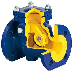 Rotary check valves, or check valves are used for very large pipeline diameters. In this design, the locking element is a spool - a “flap”. The axis of rotation of the “flap” is located above the passage hole. Under the influence of pressure, the “flap” reclines and does not interfere with the passage of water. When the pressure drops below the permissible value, the spool falls and slams the passage channel. With a pipeline diameter of more than 400 mm, rotary check valves are equipped with special devices that make the flap fit smoother and softer on the seat. Hydraulic dampers and weights installed on the flap directly or using a lever are used as such devices. A significant disadvantage of shockless structures is the impossibility of installing them on any sections of the pipeline except horizontal ones. In general, check valves have a number of advantages over check valves, including less sensitivity to contaminated environments.
S. Deineko
For centralized hot water supply systems around the world, the issue of protection against Legionella is relevant. This is especially true for branched hot water systems apartment buildings. The use of special balancing valves helps not only reduce the risk of bacterial growth, but also significantly save water
When stagnant zones form in hot water supply systems, at a certain temperature, bacteria that are dangerous to the human body - Legionella pneumophila - actively multiply in them. They are the causative agents of legionellosis, a disease with symptoms similar to pneumonia, which makes it difficult to make an accurate diagnosis.
The disease was first diagnosed in the United States after an incident that occurred in 1976 during a convention of members of the American Legion, an organization uniting veterans of various military conflicts (hence the name of the disease - “legionellosis”). Among the delegates staying in a Philadelphia hotel, an outbreak of a previously unknown disease occurred, which within a month claimed the lives of 34 of the 220 sick people.
Since then, hundreds of cases of the disease, including fatal ones, have been reported annually in many civilized countries of the world. The sources of bacteria reproduction are determined by the optimal temperature for their life activity - 20-50 ° C (Fig. 1). These are air conditioning and ventilation systems, hot water supply, and low-temperature heating.
Rice. 1. Influence temperature regime for the activity of Legionella
Legionella gets into the internal utility networks from natural sources - fresh water bodies and soil. The most suitable environment for the proliferation of pathogenic bacteria is biocolonies that form on the walls of pipelines (therefore they are less prone to this plastic pipes with a smooth inner surface) and other system elements. The risk of the formation of such substances is especially high in water supply networks with long and branched pipelines, where, due to imbalance, water stagnation occurs during the absence of water analysis.
To combat Legionella, methods such as water disinfection with chlorine or ozone are used. However, in the case of hot water supply, the most acceptable and effective is thermal exposure. It consists of maintaining a high water temperature in the system pipelines while preventing stagnation, as well as short-term heating of water to values critical for the survival of bacteria.
Balancing
DHW systems in apartment buildings are characterized by next situation- hot water when dispensing the water is flowing through the water outlet closest to the heat source. At the same time, the connection points located on the floors above receive less heated water, which has cooled down during the period of absence of water collection (for example, at night). Thus, the consumer is forced to drain this water until he gets a flow with the temperature he needs. And the longer the pipelines, the more water is drained into the sewer. As a result, there are large losses in the water supply system. In addition, the last consumer on the line may not wait hot water with standard parameters.
This is especially true for buildings commissioned in the 70-80s of the last century, in which the hot water supply systems do not have a circulation line or the circulation system does not function due to physical wear and tear.
However, even in houses with an existing circulation line, the required water temperature is not always achieved immediately after opening the water outlet. Indeed, until recently, circulation lines (T4 in Fig. 2) were equipped only on the principle of changing hydraulic resistance different diameters pipelines, that is, the diameter of the circulation pipe changed depending on the distance from the source of water heating and was less than the diameter of the supply pipeline DHW systems(T3). At the same time, the temperature in the circulation line was not controlled and not taken into account, which also led to excessive energy consumption for the operation of circulation pumps.
To avoid such situations in new buildings, special balancing valves have been installed on circulation lines for several years. They can also be used in the reconstruction of existing hot water supply systems.
These valves differ in that in addition to the specified flow rate through the circulation line, using a so-called thermal drive, it is possible to set the required water temperature in the circulation line, for example, in the range from 40 to 65 °C. If the temperature drops, the valve opens and allows water to be heated. At the same time, there is no constant need for hot water circulation. It appears only when there is no water intake in the system. The calculated value of the water temperature in the circulation line is, as a rule, no more than 5-10 °C from the water temperature in the DHW system. This indicator is influenced by:
- diameters and length of pipelines;
- air temperature in the places where the pipelines are located;
- efficiency and condition of thermal insulation.
The balancing valve allows you to adjust the water flow through the circulation line. Using a thermal drive with it makes it possible to regulate the water temperature: when it decreases in the circulation line, the valve will be open until the temperature reaches the set value. After this, the thermal drive closes the flow and the circulation pump is turned off.
Thus, through the use of balancing valves with thermal actuators, a constant temperature in the DHW system is maintained. This reduces wastage of water and also reduces the risk of bacteria development.
In Fig. Figure 2 shows the places to achieve the greatest efficiency of balancing valves in the DHW system, i.e. they should be located after the last water point. There are modifications of balancing valves with thermal drives for systems that provide thermal disinfection of water.
 Rice. 2. Scheme of the DHW circulation system with balancing valves
Thermal disinfection
To completely destroy legionella in hot water supply systems, a boiler briefly heats the water in the system to temperatures critical for the life of bacteria - for example, above 60 ° C for half an hour. As a rule, this is done at night without drawing water.
The thermal drive (Fig. 3) of balancing valves intended for systems with thermal disinfection operates according to to the following principle. When the temperature increases above 62 °C, the drive does not close, but, having reached the limit, on the contrary, opens.
 Rice. 3. Thermal drive
Structurally and technically, this works in a rather original way. An insert made of a rod with a certain set of washers, with a large increase in temperature, falls beyond the flow shutoff limit. The process occurs due to mechanical expansion. But if the temperature rises above 72 °C, the valve will close again (Fig. 4) to avoid thermal burns to consumers.
 Rice. 4. Adjustment characteristics of balancing valve with thermal disinfection function
The thermal disinfection function is supported by many modern controllers, for example, the Smile type (Honeywell). When carrying out this process, it is important that the required high temperature is achieved at all points in the system. Therefore, the pump must be switched on in increased circulation mode, and automatic balancing valves must ensure the desired hydraulic balance.
In private buildings and in apartments with an electric boiler, disinfection can be carried out manually. Periodically (once a month) heat the boiler to maximum and drive water through the system. This is especially recommended before seasonal use of the boiler (during summer outages of centralized hot water supply).
Device examples
The installation of balancing valves on recirculation lines of hot water systems has been practiced in Ukraine relatively recently - about 3-4 years. Nowadays, in new buildings with an extensive hot water supply system, their installation is mandatory. After all, without hydraulic balancing, for example, for multi-storey building with 6-10 entrances and with several risers in each, it is almost impossible to hydraulically “link” the circulation lines of the first and last entrances.
It is important to know that in DHW systems it is not permissible to use balancing valves intended only for heating systems. Indeed, despite the similarity of the tasks being solved, there are a number of features. For example, valves for circulation systems DHW systems are made from materials that are resistant to corrosion and meet the relevant hygienic requirements.
Balancing valves for domestic hot water systems produced by Danfoss companies(Denmark), Honeywell (Germany), Oventrop (Germany) and others.
For example, balancing valves for DHW Alwa-Kombi-4 (Honeywell) (Fig. 5) are made of corrosion-resistant red bronze Rg5. Hydraulic balancing is carried out by manual installation water flow through the valve, according to calculations of the required pressure drop for each circuit. For automatic regulation water temperature, the valve is equipped with a thermal actuator. In the standard version, it helps maintain the required water temperature in the range of 40-65 °C (insert with a black cap); in the special version, a thermal drive is provided with a function to support thermal disinfection (supplied with an orange cap). The Alwa-Kombi-4 can be retrofitted with a thermal drive at any time, including after installation on the system. The valves are resistant to high temperatures(up to 130 °C) and pressure (up to 16 bar). Diameters - from 15 to 40 mm.
 Rice. 5. Balancing valve for DHW system (Alwa-Kombi-4)
There are also automatic mixing valves that ensure a constant water temperature after mixing. They are installed both at individual water points (washbasin, shower, etc.) and in small groups of them, for example, in children's rooms. preschool institutions or schools.
Backflow protection
To protect water supply systems from the ingress of contaminants and pathogenic bacteria during gusts or penetration through counterflow, special cut-off devices (Backflow Preventer, English - “backflow prevention device”) are used in EU countries.
According to European standards EN 1717, they must be installed at every water supply installation - at the entrance to buildings, as well as on distribution lines - right up to the apartment. The purpose of their use is to prevent contaminated water from entering the centralized water supply system.
The devices have three chambers (Fig. 6), which close in the event of a sharp decrease in inlet pressure or an increase in the back pressure of water from the consumer. In this case, the contaminated water is cut off and drained into the sewer. Thus, unwanted impurities do not enter the internal and external networks of the water supply system.
 Rice. 6. Backflow prevention device (BA-295, Honeywell)
There are various modifications of shut-off valves, depending on the category of buildings. However, they have not yet received mass distribution in Ukraine due to the lack of domestic standards for their mandatory use.
More important articles and news in the Telegram channel AW-Therm. Subscribe!
Views: 8,083A three-way mixing valve is designed to mix two incoming flows (cold and hot) into one outgoing flow at a given temperature. These valves are especially in demand in domestic hot water supply systems to protect consumers from scalding. They can also provide hot water directly from instantaneous or storage water heaters or be used as a preliminary mixing stage. They are no less often used to maintain a stable supply temperature in underfloor heating systems.
Operating principle.
Internal regulation of the valves is carried out automatically due to the presence of a temperature-sensitive element that is in contact with the mixed flow and contracts or expands depending on the deviation of the mixture temperature from the set output value, thereby increasing or decreasing the inlet openings of the hot or cold water.
How does burn protection work?
Most thermostatic valves currently on the market have a temperature protection device - “scald protection”. In the event of an unexpected interruption in the supply of cold water to the valve, the supply of hot water is automatically shut off, thereby eliminating the possibility of supplying hot water without prior mixing to the consumer.
Direction of flows.
There are two schemes for directing flows in a thermostatic valve - symmetrical and asymmetrical. The choice of a specific scheme depends on the type of installation and ease of installation in a particular heating or hot water system. Let's take a closer look at each of them.
GW- hot water;
HV- cold water;
NE- mixed water.
Symmetrical T-shaped flow direction diagram
Cold and hot water are supplied from opposite sides, mixing occurs in the middle. This scheme is very common in Europe, due to the compactness of the valves.
Asymmetrical L - shaped flow direction diagram

Hot water is supplied from the side, cold water is supplied from the bottom. It became widespread due to the versatility and simplicity of the resulting mixing unit.
Examples appearance thermostatic valves with symmetrical and asymmetrical flow direction:
 |  |  |
Watts AquaMix (Germany) | Danfoss TVM-H (Denmark) |
Exactly about thermostatic valves The asymmetric flow arrangement will be discussed further.
Areas of application for thermostatic mixing three-way valves.